16
EN
General Information VARC Chiller Controls
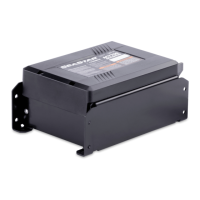
4. Scroll down to view version information.
5. Repeat for each stage.
Verify that all stages have the same version number. In
the unlikely event that there is a difference between
stages, the PCB firmware must be updated by a
Dometic-approved technician.
5.5 Networking
When setting up the stages for networking, ensure that
the chillers are not connected via Modbus connections.
Stage 1 requires minimal changes, so start with stage 2,
leaving stage 1 until last.
To set up networking, follow these steps:
1. Power off all stages except stage 2.
2. Press the Program button. See “LCD Buttons” on
page 5.
3. Go to Technician.
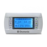
4. Scroll down to Service settings, then press Enter.
5. For Service Password, enter 3156.
6. Go to Stage Address.
7. Press Enter, then change address to 2 for chiller 2, 3
for chiller 3, and so forth.
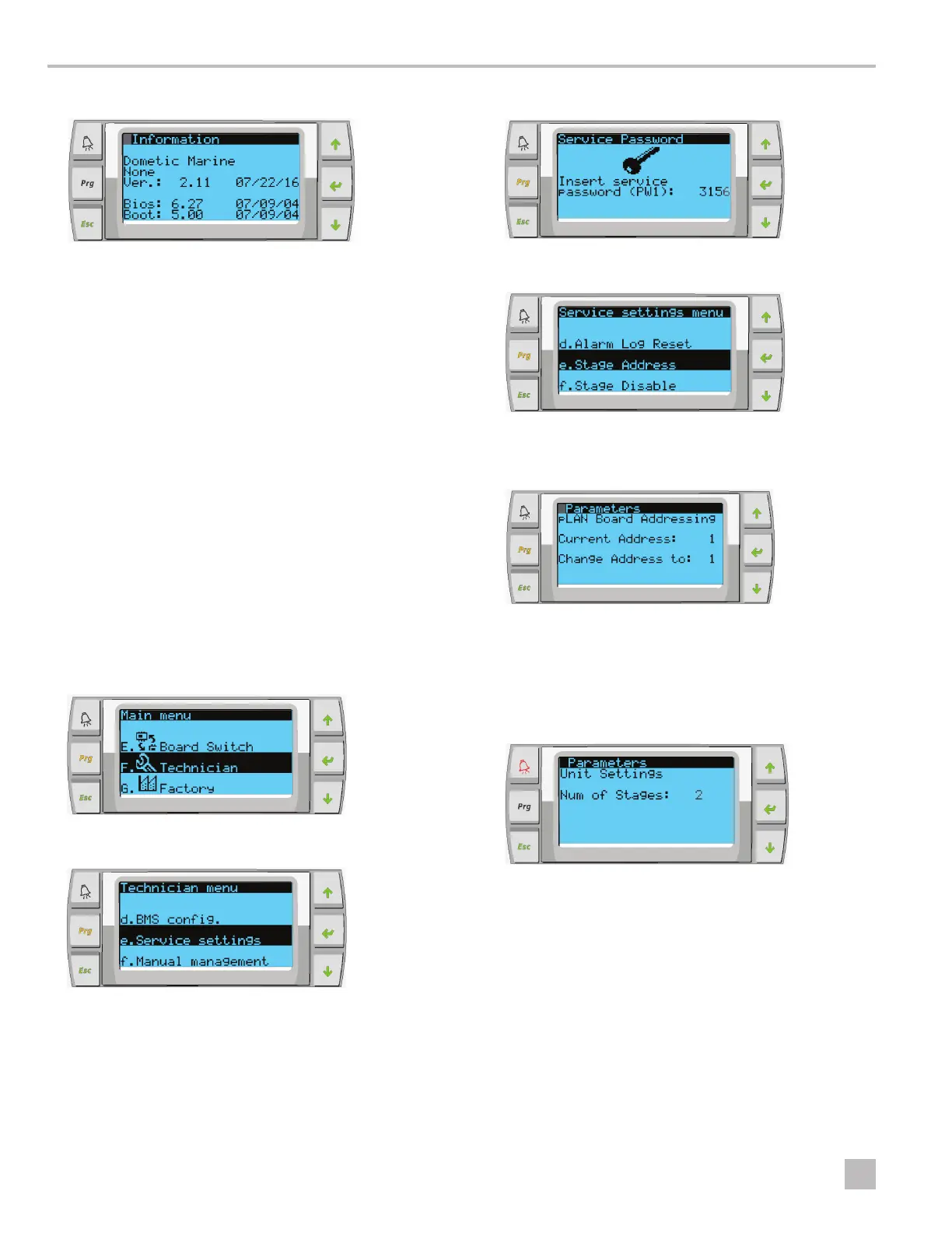
8. Press the Scroll Down button to display the next
screen and change the number of stages. Press Enter
until the cursor is on Num of Stages, then change
from 1 to the correct number of stages for the current
system.
9. Repeat steps 2-8 for additional stages.
10. For stage 1, only perform step 8 to change the total
number of stages.