EasyManuals Logo

Dometic PGD1 User Manual

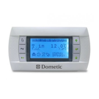
Dometic PGD1
48 pages
To Next Page IconTo Next Page
To Previous Page IconTo Previous Page
Page #14 background imageLoading...
Page #14 background image
14
EN
General Information VARC Chiller Controls
5 Electrical Connections VARC 60/72
5.2 Multi-stage Wiring
The following diagram shows how to wire multiple VARC stages.
24VAC/DC
L2
CW Return Manifold
CW Supply Manifold
Circ. Pump Sea Pump
CW L1
VARC
Stage 1
Chiller
Stage 1
Chiller
Stage 2
Chiller
Stage 3
VARC
Stage 2
VARC
Stage 3
SW L1
Supply
Supply
Supply
Return
Return
Return
Flow Switch
Flow Switch
Flow Switch
Freeze Stat
Freeze Stat
Freeze Stat
GND
Touch Screen (optional)
Modbus Comm 3 Wire
Pump Outputs from VARC Stage 1
Remote PLC Display
(Optional)
3 Wire Communication
Cables (one per stage)
6 Multi-Stage Wiring Diagram

Questions and Answers:

Question and Answer IconNeed help?

Do you have a question about the Dometic PGD1 and is the answer not in the manual?

Dometic PGD1 Specifications

General IconGeneral
BrandDometic
ModelPGD1
CategoryControl Unit
LanguageEnglish

Related product manuals