PSS5000/CONF/804473/40 9 of 54
PSS 5000 – Hardware Configuration Guide
Selecting the CPU Board and Interface Modules
9. You are now ready to connect the selected HIMs to the CPU Board.
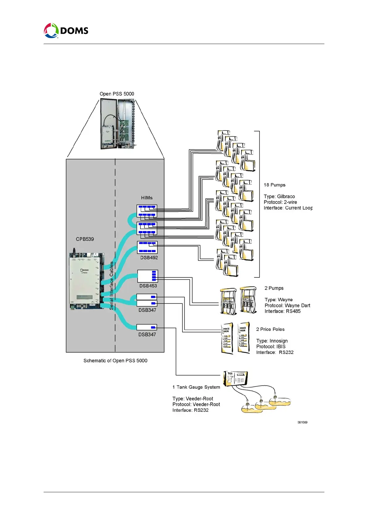
The figure below shows the devices connected to a CPB539 board through
the HIMs and the associated serial interface cables.
Note: This illustrates that only 16 devices using the Current Loop interface
can be connected to a single port (2 of the DSB492 HIMs are daisy
chained together and connected to a single port). Under normal cir-
cumstances, we recommend that load balancing is used on the ports
when connecting multiple devices (with the same protocol) to mul-
tiple modules – this increases performance.
 Loading...


