Power Train Disassembly & Assembly
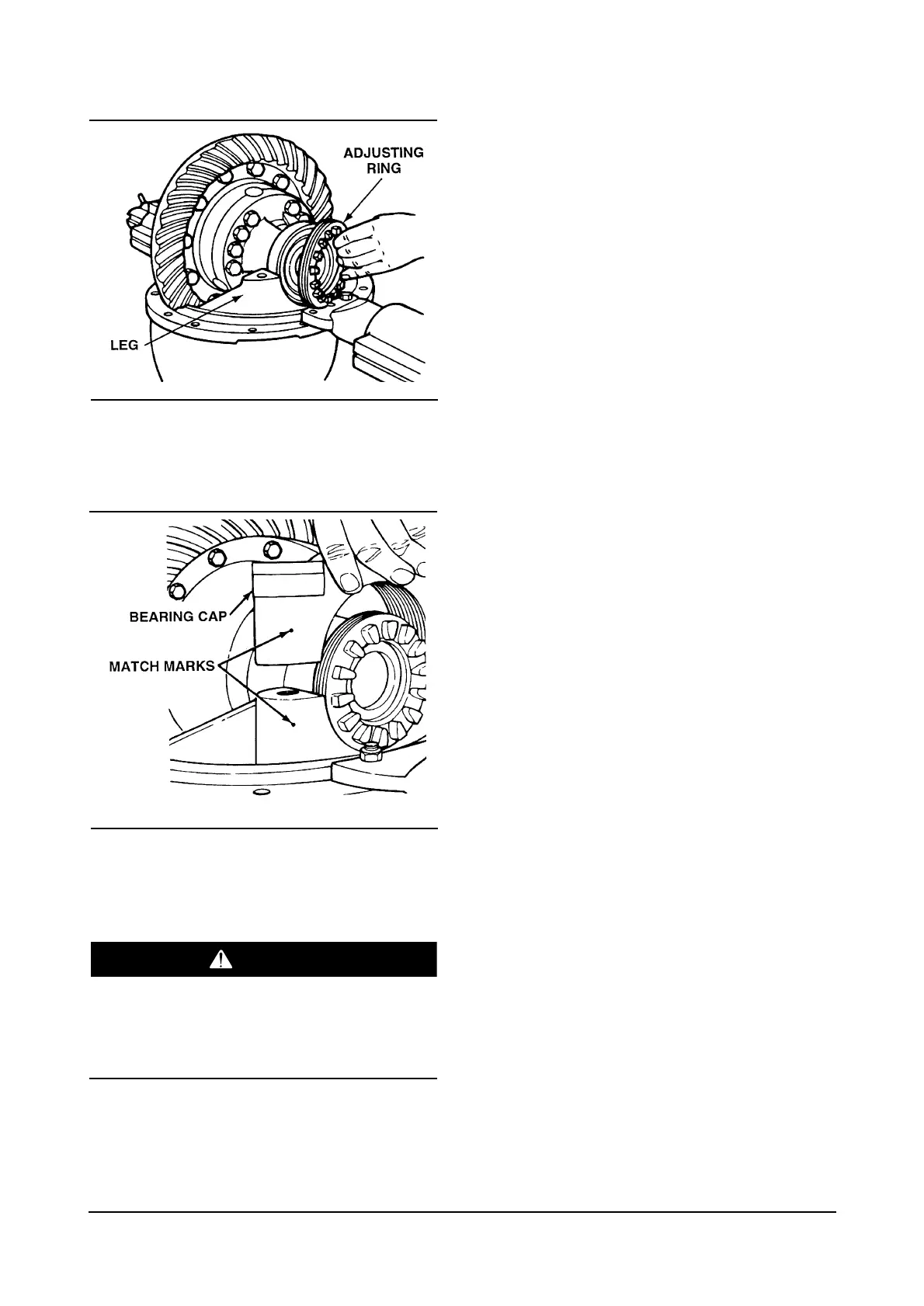
6. Install both of the bearing adjusting rings into
position between the carrier legs. Turn each
adjusting ring hand-tight against the bearing cup.
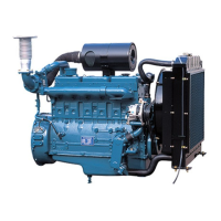
7. Install the bearing caps over the bearings and
adjusting rings in the correct location as marked
before removal.
Do not hit steel parts with a steel hammer during
removal and disassembly procedures. Striking
parts with a hammer can cause the parts to break
and result in serious personal injury.
8. Seat each bearing cap with a light leather, plastic
or rubber mallet. The caps must fit easily against
the bearings, adjusting rings and carrier. DO not
force the bearing caps into position.
CAUTION : If bearing caps are not installed in
correct locations, the bores and threads in caps will
not match the carrier. You will have problems
assembling the caps on the carrier and damage to
parts can occur. Do not force the bearing caps into
position.
9. If bearing caps do not correctly fit into position,
inspect the alignment of match marks between
caps and carrier. Remove the caps and repeat
steps 6-8.
10. Install the capscrews and washers that hold
bearing caps to the carrier. Tighten the
capscrews by hand four to six turns, then tighten
the capscrews to a torque of 347 to 431 lb•ft (470
to 585 N•m).
NOTE : Do not install the cotter keys that hold the
bearing adjusting rings in position. Continue by
adjusting the preload of differential bearings, adjust
backlash of the hypoid gear and inspect tooth contact
patterns.