1.
2.
4
A
B
1
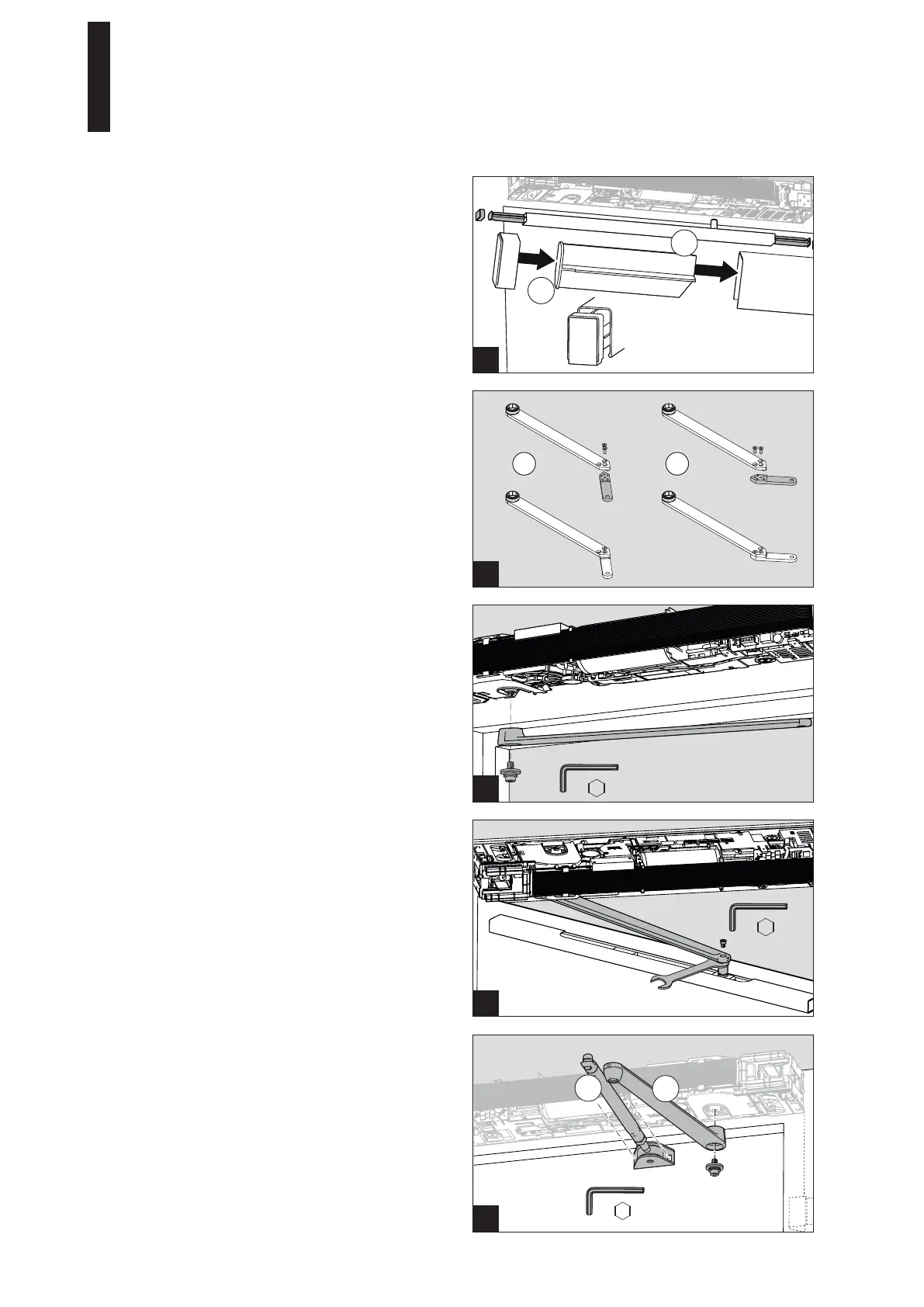
5. Place the end caps onto the spacers.
6. Guide the spacers and the end caps into the cover.
Ensure that the installation position is correct; the
spacers and end caps must be installed as shown in
the figure.
7. Align everything such that the end caps on both sides
are flush with the cover.
2
2. Screw the lever down to the slide shoe.
5.9 Installing the Standard Arm
1. Screw the clamping screw (A) down into the prepared
holes with 2 screws.
2. Screw the lever (B) onto the drive axle with a high
torque (35 Nm).
Use only the self-locking screw provided. If this screw
is loosened during repair or maintenance work, it must
be replaced by a new self-locking screw
(see spare parts list).
1
5.7 Installing the Slide Channel Lever CDP
If using the slide channel lever CDP, it must be assembled.
1. Screw the lever together in a way that suits the
installation situation.
1 Hinge side DIN right and
opposite hinge side DIN left
2 Hinge side DIN left and
opposite hinge side DIN right
1
5.8 Installing the Lever
1. Screw the lever onto the drive axle with a high torque
(35 Nm).
Use only the self-locking screw provided. If this screw
is loosened during repair or maintenance work, it must
be replaced by a new self-locking screw
(see spare parts list).
1 2
35 Nm
35 Nm
5 mm
5 mm
5 mm
WAF 13 mm
ED 100, ED 250
—
19DORMA