10
11
12
brown
black
red
9
8
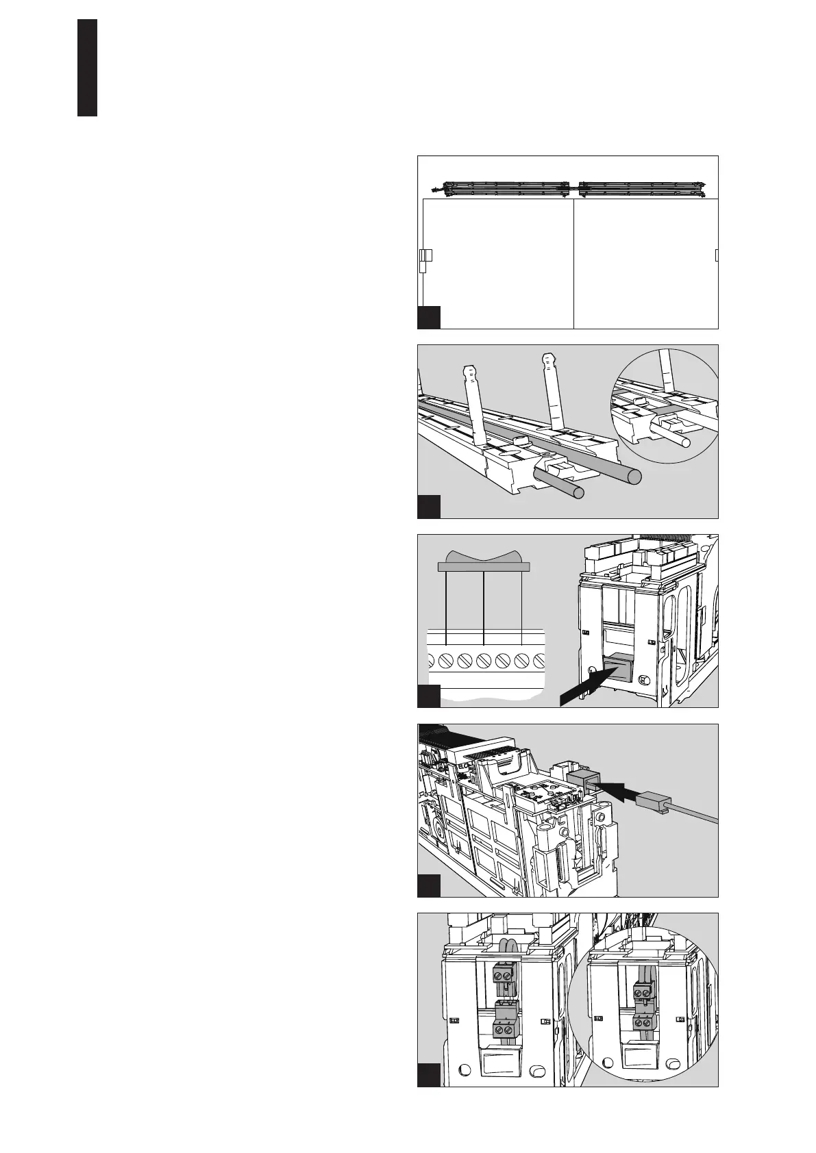
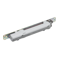
16. Clip the new program switch into the holding fixture of
the removed mains switch and connect it to the drive
for the active leaf.
Connection takes place on the terminal board at the
terminals for the external program switch.
17. If the program switch has been installed on the drive
for the active leaf, the connection cable must be
shortened.
The cable ends must be equipped with cable lugs.
18. Insert the communication cable into the two
“horizontal” plugs on the control unit.
19. Connect the mains connection cable for the second
drive.
Figure 12 shows the connection on the active leaf.
14. Lay the mains connection cable for the second drive
and, if necessary, the program switch cable in the
groove of the mounting plates and fix them with the
enclosed plastic platelets.
If the system is to be equipped with a closing sequence
control, install it now (see installation instructions
ED 100/250 ESR WN 057380-45532).
15. Install both drives
(see page 17, point 5.4).
11. Screw the mounting plates down into the prepared
holes with 12 screws each.
Use dowels and screws adapted to the substructure for
fixing.
12. Hammer the supplied retaining pins into the bottom of
both holes with a hammer.
13. Connect the 230 V connection line
(see page 17, point 5.3, figure 2).
ED 100, ED 250
—
24 DORMA