97 98 99 30 31 32 34 33 3335
1
36
1
4
4a
3
BA
1
57 57a
142
3
141
3
1
15
17
3
111
13 3
43 3646362
1G
3
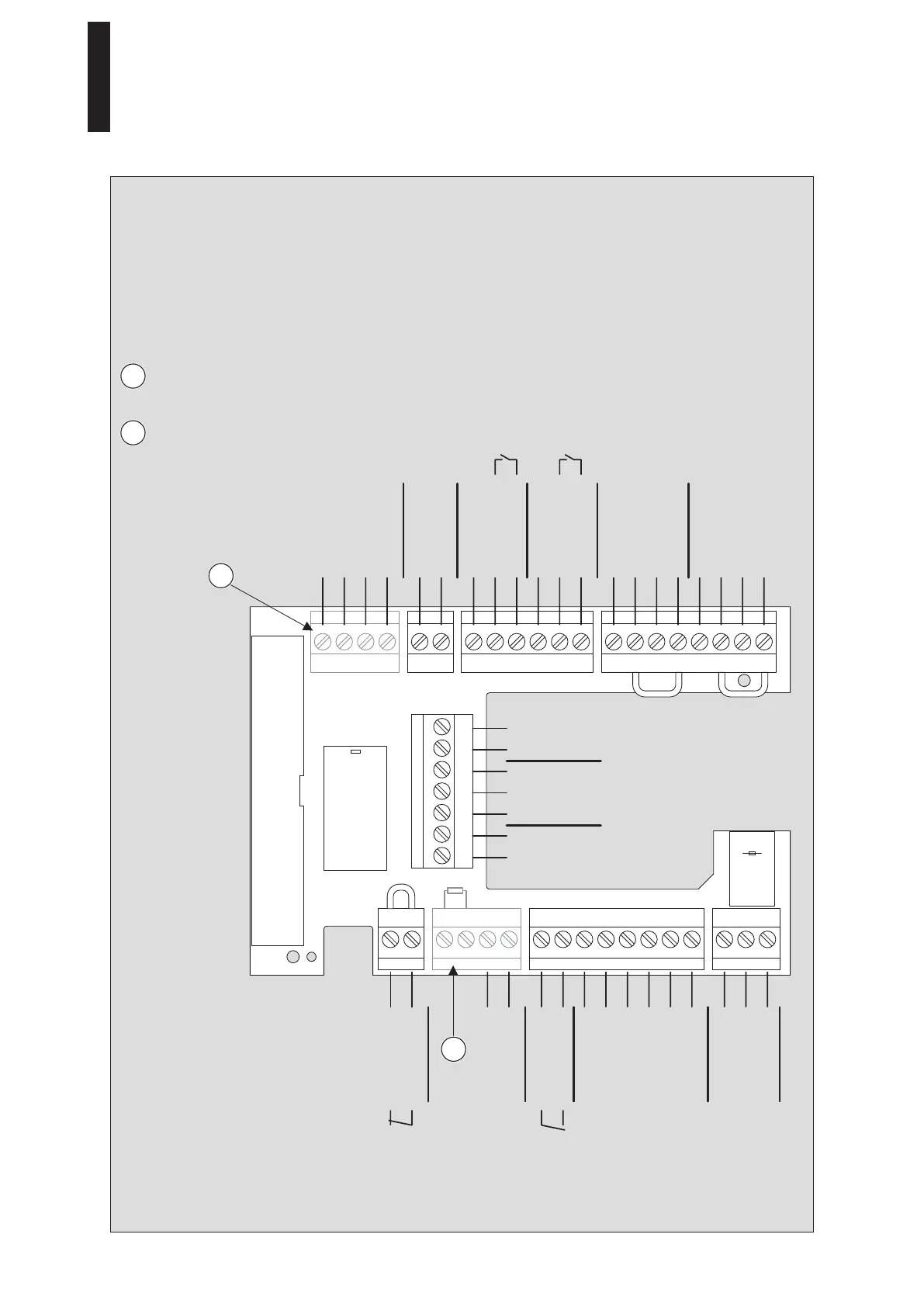
6. Connecting Accessories
1. Connect the connection lines to the plugs and insert the plugs into the terminal board.
• The maximum overall load on terminals 1, 1G and 3 is 1.5 A.
• The maximum cable length when using J-Y(ST)Y 0.8 mm is 30 m.
6.1 Terminal Assignment
Terminal included in the DCW
Upgrade Card scope of delivery.
Terminal included in the Fire Protection
Upgrade Card scope of delivery.
0 V
B
A
8 – 24 V DC/AC + 5%
+ 24 V
+ 24 V
Signal input
0 V
+ 24 V
COM
Locking device relay
max. 1 A / 48 V DC/AC
NO
NC
0 V
Locking device feedback
0 V
+ 24 V
Signal input
0 V
0 V
+ 24 V
0 V
Signal input
0 V
Partial open
Permanent open
Output
Automatic
Off
NC
NO
max. 1 A / 48 V DC/AC COM
0 V
Signal input
Test output
+ 24 V
0 V
Signal input
Test output
+ 24 V
0 V
Night/Bank
Deactivation of
drive function
Smoke
detector
Night/Bank
Program
switch
Status
relay
External
pulse
Internal
pulse
Safety sensor
on hinge side
Safety sensor on
opposite hinge side
DCW
1
1
2
2
ED 100, ED 250
—
26 DORMA