10. Diagnosis / Troubleshooting
DORMA drives satisfy a high safety standard and comply
with all the necessary technical rules and requirements.
Both internal safety circuits and external safety circuits
managed by the drive are monitored on a cyclical basis.
While the devices are in use, situations that result in an error
message may arise.
The drive attempts to identify the cause and respond
accordingly. The response depends on the severity of the
cause and extends from providing information to deactivating
the drive’s automatic function.
In this case, the drive switches to emergency mode and acts
as a door closer.
The door can be used manually.
Information “In” and error messages “E0” to “E9” are
shown on the user interface’s display and indicated by
means of the red LED on the internal program switch.
The output on the LED takes place in code. Refer to the
table of errors regarding this matter.
Error messages “E0” to “E9” are stored in the error memory
and can be read out from the user interface’s display or
with the DORMA hand-held terminal. Currently active error
information is always assigned to error message memory
location E0. When another error occurs or when this error is
acknowledged, it is moved to error message memory location
E1.
A maximum of nine errors can therefore be saved in the
E1 – E9 error memories. Identical error messages which
occur one after the other are not saved again.
Briefly press
to call up error messages E0 to E9.
Dealing with Information (“In”)
Information serves to make the drive easy to service and
indicates both faulty statuses and operating statuses that
suppress the drive’s automatic mode.
For example:
In 08 -> Emergency stop has been pressed; the drive does
not perform any automatic functions.
In 01 -> Blocking was detected; the drive continues to
work.
Information can be turned into an error message if it occurs
repeatedly.
Handling Error Messages “E0” to “E9”
Error messages indicate a hardware defect. However,
installation errors and manual operation during safety tests
can also cause error messages, and the system switches
to emergency mode. The following options are available for
resetting error messages:
• Switching the program switch to OFF or resetting by
pressing the Reset button on the user interface when
the cover is open.
• Mains reset. Switch off the mains switch. Switch it
back on again after 10 seconds.
The cause should always be analyzed and remedied before
an error message is acknowledged. The table below is
intended as a guide.
Malfunction Possible Cause Remedy
The door can be used only
manually or the door does
not open automatically
after an opening pulse has
been generated.
Check the green LED.
If the green LED does not light up,
there is a problem with the power
supply.
The mains switch must be switched on.
The mains power supply must be checked and restored
if necessary.
If the power supply is on, but no 24 V DC is available,
the power supply unit must be replaced.
Check the red LED.
If the red LED on the mains switch
flashes, the control unit has detected
an error and emergency mode is
activated.
Troubleshooting instructions can be found in the
Information and Error Messages list.
The program switch is in the “Off” or
“Output” position.
Move the program switch into the “Automatic” or
“Permanently open” position.
There is a signal from the safety sensor
on the hinge side and this is preventing
the door from opening.
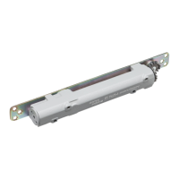
The safety sensors’ signals are shown directly on the
user interface’s LED display with the
two decimal points for
diagnostic purposes.
The respective decimal point lights up if something has
been detected.
The sensor’s wiring and function must be checked.
If the LED in the top left-hand corner flashes, wall
blanking is active. No error is present.
ED 100, ED 250
—
37DORMA