06-2023 dormakaba Canada Inc. RAC5 MFC Installation Guide – PK3738 | 31
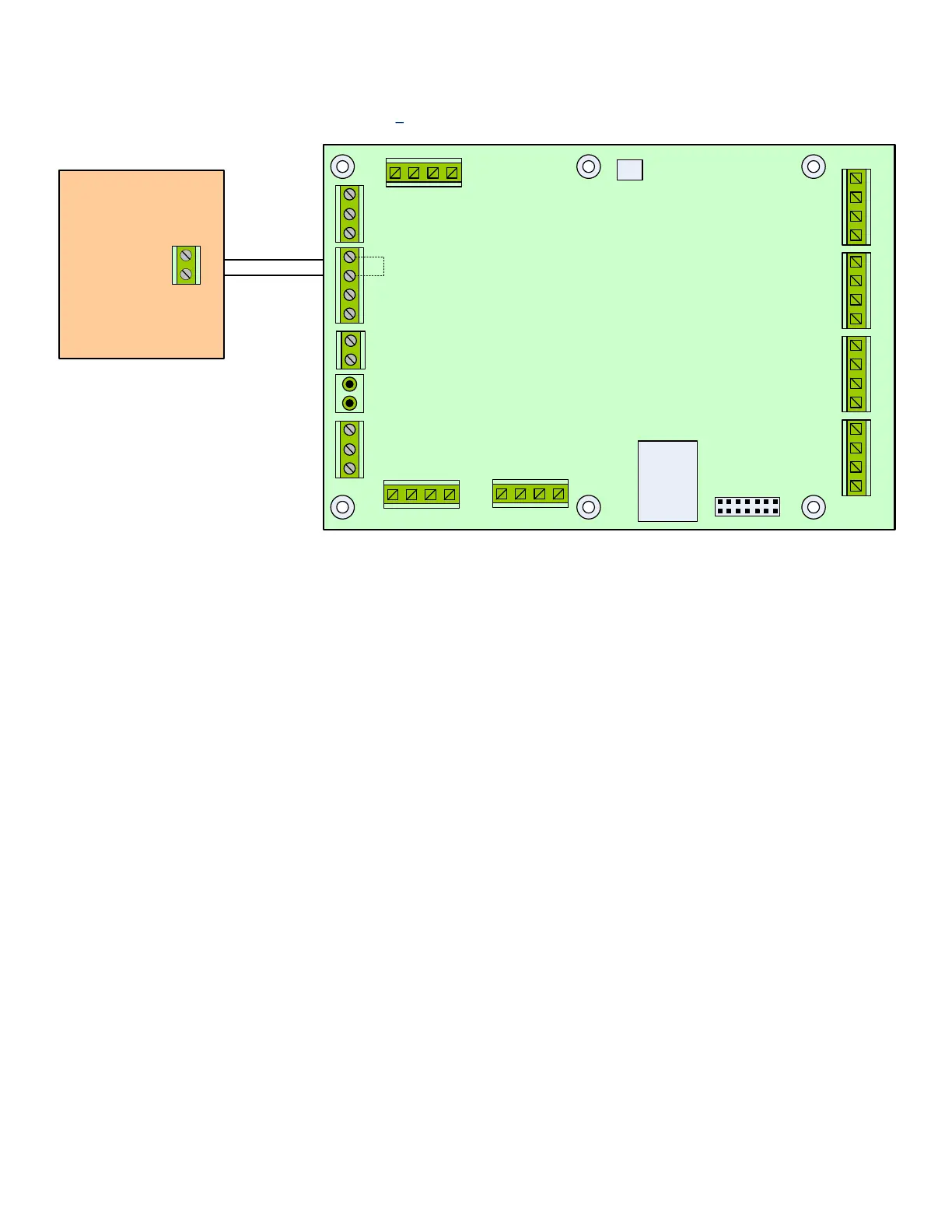
11 Annex H: Access Override Panel Wiring
Figure 21 Access Override Panel Wiring
Normally
Closed
Output
Access Override
Panel
Note 2: If the Access Override Panel connection is not required, place a jumper
wire between pin 3 and 4 of J18.
Note 1: The input from the Access Override Panel must be connected to a
Normally Closed Dry contact. When the RAC5 MFC Access Override is
activated, power to all relays will be removed. Ensure you have configured
Switch 4 of the Relay Expansion Board appropriately for your desired controller
behavior. See Switch 4 configuration details referenced on page 12.
1 2 3 4
1 2 3 4
1 2 3 4
J17
J3
J7
J8
J12
J1
J15
J16
J6
J18
J19
RAC5 MFC PCB
NO NC COM
GND FIRE GND 12V_LCK#1
GND 12V NO NC COM
RE_UNL#2
GND
RE_UNL#1
1 (+) 2 (-) 3 (+) 4 (-)
1
2
3
4
1
2
3
2
1
1
2
3
12_LCK#2 GND
1 2 3 4
PWR GND GND PWR
RD#1 RD#2
READER 2 READER 1
1 2 3 4
J11
REX2 GND
TAMPER
GND
DOOR
STAT#2 GND
GND
REX#1
GND
DOOR
STAT#1
GND
GND LOW_BAT AC_ FAIL
4 3 2 1
NC
COM
(Not supplied by dormakaba)