Service maintenance manual
8.11 Removing and installing RJ45 connector and Ethernet cable
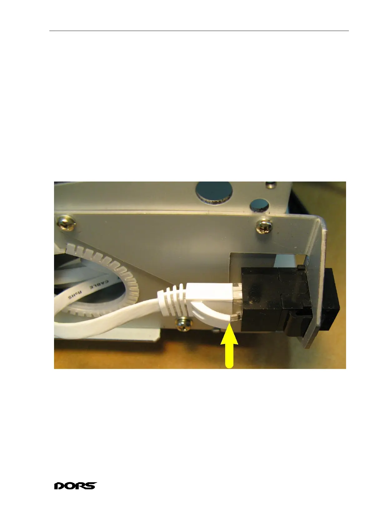
8.11.1 Press the Ethernet cable clamp and remove the cable from the RJ45 connector (see Fig.
114, Fig. 115).
8.11.2 Press the movable retainer of the RJ45 connector and remove the connector from the
holder (see Fig. 115, Fig. 116).
8.11.3 If you need to remove the Ethernet bracket, take out three M2.5x6 N0039 screws (with
spring washers 2.5 W0031) securing the bracket to the side wall (see Fig. 117).
8.11.4 To replace the Ethernet cable, it must be removed from the ties (see Fig. 52, Fig. 51, Fig.
55, Fig. 50, Fig. 64, Fig. 65, Fig. 85) and disconnected from the Ethernet module by pressing the
clamp on the Ethernet cable (see Fig. 85).
8.11.5 The installation of the RJ45 connector and the Ethernet bracket is in the reverse order.
The Ethernet cable must be routed and fixed with ties (if they have been removed) as
described in sections 8.4. Wire dressing, 8.6. Removal and installation of hopper unit.
Fig. 114
 Loading...