Service maintenance manual
Fig. 63
Fig. 64
Fig. 65
8.5 Removal and installation of Drivers module
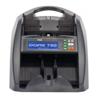
8.5.1 Disconnect the cables from the connectors of the Drivers module X1, X2, X3, X4, X6,
X7, X8, X9, X10, X11, X12, X13, X14, X15, X16. (Fig. 66. Fig. 70). If necessary, remove the cable
ties.
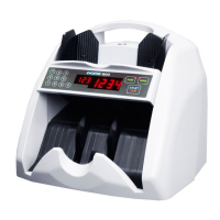
8.5.2 Lift the clamps of connector X5 from both sides; carefully remove the FFC (Fig. 67, Fig.
68, Fig. 69).
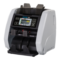
8.5.3 Unscrew four screws M3x6 N0019 + W0022 + W0007 / JPM1-306N1H04 holding the
Drivers module, remove the plastic washers, remove the module (see Fig. 70, Fig. 71).
 Loading...