Service maintenance manual
8.12 Removing and installing Raspberry Pi module
8.12.1 If necessary, remove the SD memory card from the Raspberry Pi connector (see Fig. 119,
Fig. 121).
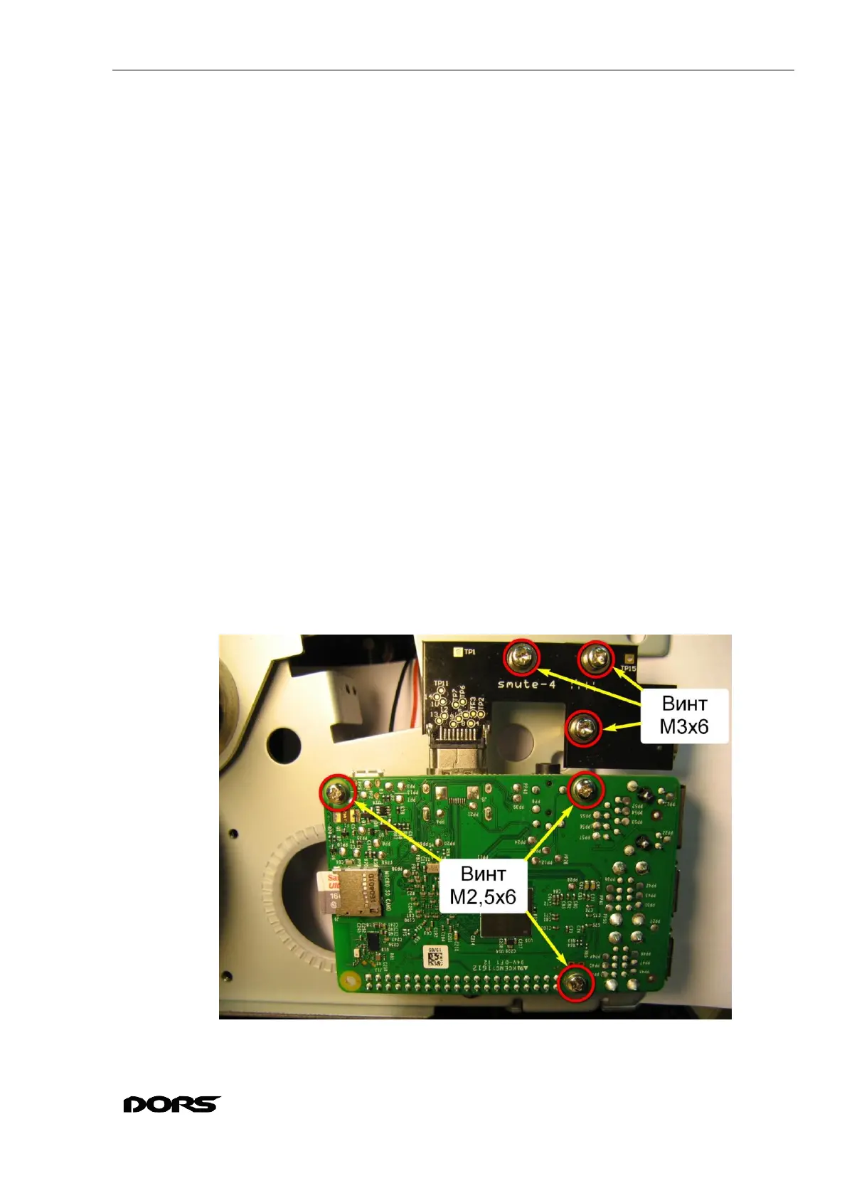
8.12.2 Remove three M2.5x6 screws with washers from the Raspberry Pi module; remove three
M3x6 screws (with washers) from the HDMI connector board, and carefully remove the modular
assembly for the length of Raspberry Pi cable (see Fig. 118, Fig. 120).
8.12.3 Disconnect Raspberry Pi cable; disconnect HDMI connector board (see Fig. 120, Fig.
121).
8.12.4 If it is necessary to remove the PCB stands, disassemble them with an adjustable wrench.
Assembly and installation of modules is done in the reverse order. The stands should be
fixed with the adjustable wrench.
ATTENTION: do not mix up the stands in their places: M2.5 hexagonal rails 22 mm are
for the Raspberry Pi module, 18 mm M3 hexagonal rails are used for the HDMI connector
board (see Fig. 122).
To replace the Raspberry Pi cable, it must be removed from the screeds (see Fig. 49, Fig.
53), disconnected from the X12 connector of the BVS module (see Fig. 113), disconnected
from the adapter module X7 connector of the BVS (see Fig. 106) .
Connect Raspberry Pi cable as shown in Fig. 120. Place the Raspberry Pi module so that
the connector is located in the upper left corner. The cable connector is oriented so that the
red wire is on the left. Connect the cable to the left of the end contacts. Make sure that the
cable is securely fixed and does not drop out.
Raspberry Pi cable should be laid and fixed with ties (if the ties have been removed) as de-
scribed in section 8.4. Wire dressing.
Fig. 118