3.3
M
M
JY (St) Y
4x2x0,6
230VAC
24VDC
JY (St) Y
2x2x0,6
JY (St) Y
2x2x0,6
JY (St) Y
2x2x0,6
JY (St) Y
2x2x0,6
JY (St) Y
2x2x0,6
JY (St) Y
2x2x0,6
JY (St) Y
4x2x0,6
JY (St) Y
4x2x0,6
JY (St) Y
4x2x0,6
11/48
LSC 44-M4
99.823.35 1.2/06/09
fire
detector
Key-
operated
vent button
external control
BMS
signal contact
lift
Signal contact
BMS/MSR
smoke
vent button
RT 43-LSC
230V 50Hz
not possible to switch off
control
panel
drive
rain
detector
acoustical signal
transmitter
flashing
light
signal
indicating board
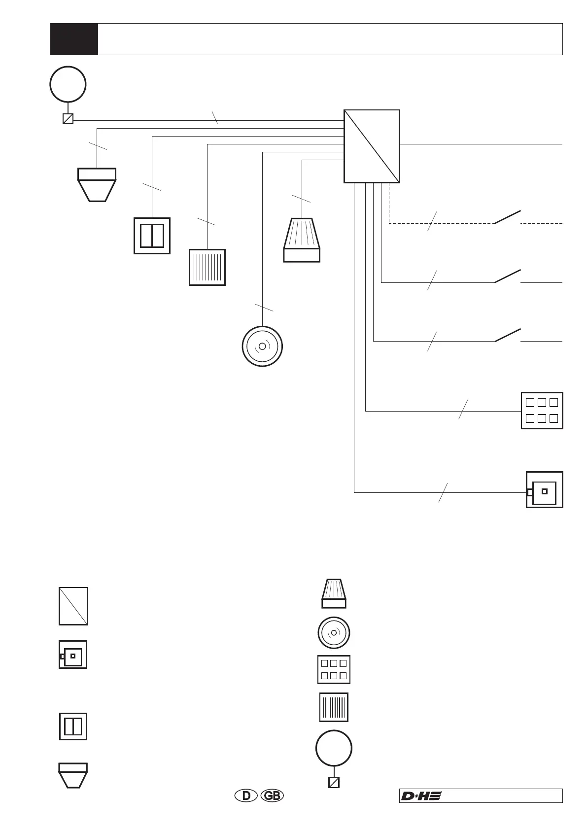
Symbol Description
Wiring Plan Lift Shaft
LSC 44-M4 surface type
600x600x210 (230VAC/ 24VDC)
near the lift shaft
Smoke vent button (RT 43-LSC)
surface 24 VDC circa 1,5m above
upper edge firm flooring (by customer
55mm flush socket)
Vent button 24 VDC (e.g. LT 43) circa
1,2 above upper edge firm flooring (at
flush type by others 55mm flush
socket)
Fire detector 24 VDC
(e.g. FO 1362 or FT 1262)
230V- Power supply
Weak Current Lines
Provide for separate electric circuit.
Mark fuses.
Connecting cable
Install and feed separately from supply mains.
Mark cable and terminal box red.
: NYM-I 3x1.5
Connecting load : RZN 4404-M = 120 VA
flashing
light
acoustical
signal transmitter
signal
indicating board
rain
detector
Drive 24 VDC at smoke vent flap (lines
must end in flush mounted distribution
box, see symbols above).
see cable
wiring table
230VAC
24VDC
 Loading...