20 DR
®
ROTO-HOG™ POWER TILLER
Connecting the DR ROTO-HOG POWER TILLER to your Tow Vehicle
The following procedure is for connecting the DR
ROTO-HOG POWER TILLER to your tow vehicle.
1. Back up your Tow Vehicle so that the Hitch
of the Vehicle is in line with and next to the
Hitch on the DR ROTO-HOG POWER
TILLER. Set the Parking Brake on the Tow
Vehicle.
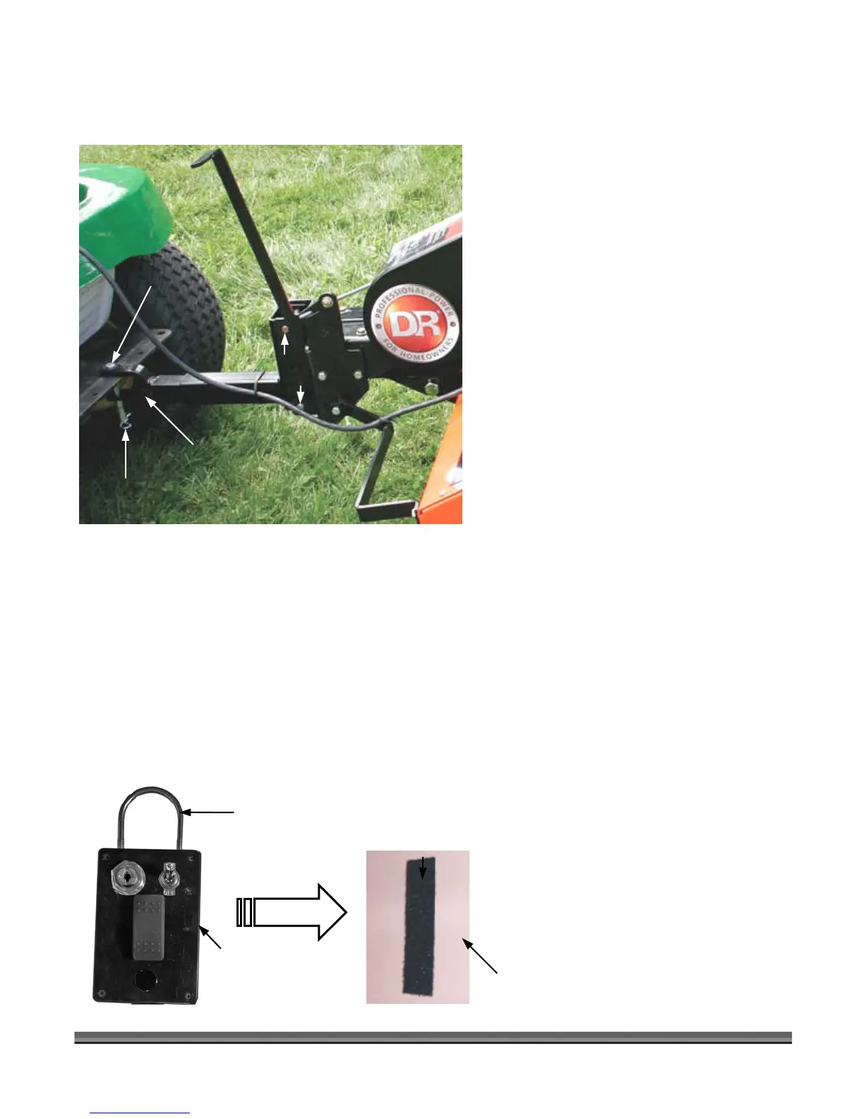
2. Adjust the height of the Clevis on the Hitch
on the DR ROTO-HOG POWER TILLER
using the Control Box for the Actuator so
the Clevis is ready to attach to the Hitch of
the Tow Vehicle.
NOTE: The height of machine is adjustable by +/-
3" by removing the two (2) Clevis Pins
(Figure 11) and re-positioning the Hitch
up or down. The lower the front of the
frame, the deeper the Tine depth for
tilling, but you will lose transport height.
3. Remove the Hair Clevis Pin and Clevis Pin
from the Clevis. Back the Tow Vehicle so
the Hitch on the Tow Vehicle goes into the
Clevis. Set the Parking Brake on the Tow
Vehicle and reinstall the Clevis Pin and Hair
Clevis Pin (Figure 11).
Attaching the DR ROTO-HOG POWER TILLER Control Box
The following procedure includes the steps necessary for attaching the DR ROTO-HOG POWER TILLER
Control Box to your Tow Vehicle. There are two (2) options for attaching the Control Box:
• Hang the Control Box by the attached U-Bolt (Figure 12) in an accessible and comfortable position
on your Tow Vehicle from which you can operate the Control Box; or,
• Attach the Control Box on a clean flat surface using the self-adhesive Hook and Loop strips provided
with the DR ROTO-HOG POWER TILLER (Figure 12).
NOTE: To prevent the Control Cable from
entering the Tines during
operation, coil up any excess Cable
and secure with a Cable Tie.
Make sure you leave enough Cable
length to accommodate turns.
Figure 12
Attached U-Bolt
Control Box
Hook Strip attached to
back side of Control Box.
Clean flat surface
on Tow Vehicle.
Loop Strip
Mate up and
push together.
Figure 11
Hair Clevis Pin
Clevis Pin
Clevis
Clevis
Pins