20 DR
®
TRIMMER/MOWER
Before performing any adjustment, maintenance procedure or inspection,
stop the engine, wait five (5) minutes to allow parts to cool and disconnect
the spark plug wire, keeping it away from the spark plug.
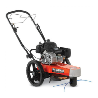
2. Looking down at the top of the Frame, turn the Mow-Ball™ Support
Assembly clockwise until it unscrews completely from the Bearing Housing
(Figure 30). Remove the Tool or Screwdriver after you have removed the
Mow-Ball™ Support Assembly.
NOTE: If the Mow-Ball
™
Support Assembly continues to turn, but does not come
off, check to be sure that you locked the Head Locking Tool or Screwdriver into the
shaft.
3. To reinstall the Mow-Ball™ Support Assembly, reverse the above
instructions.
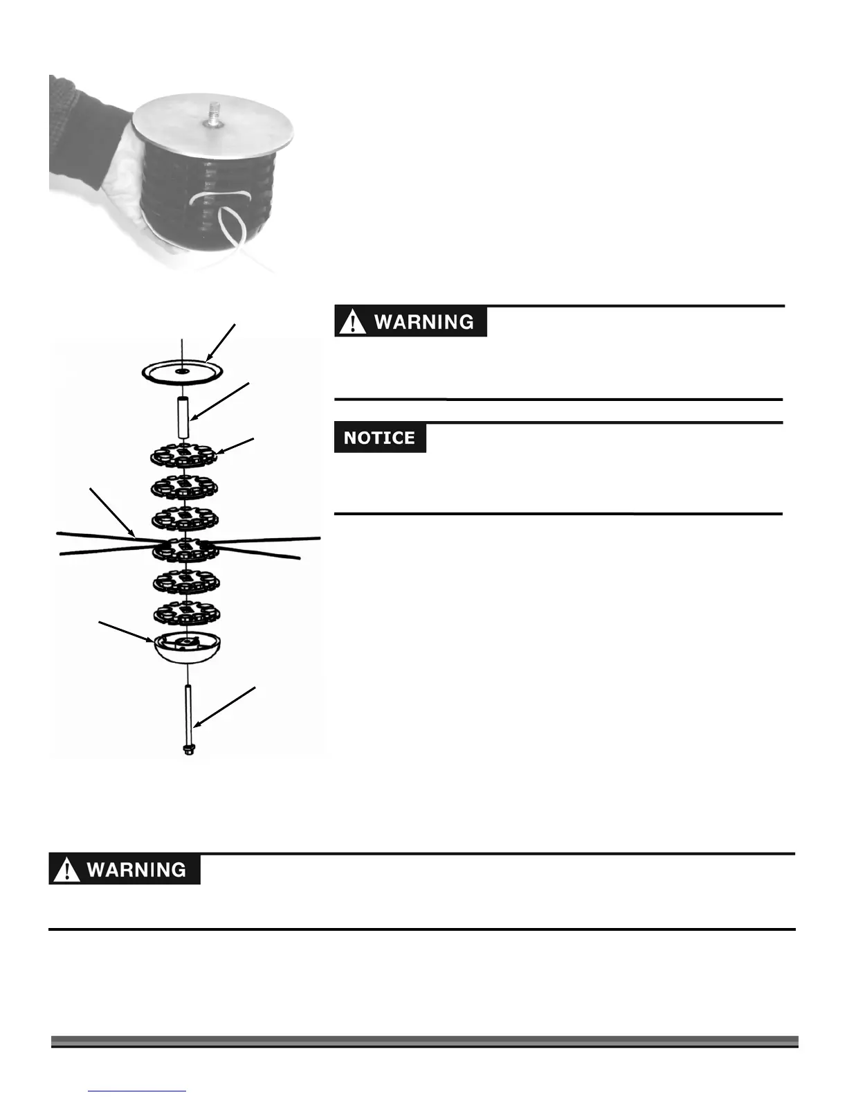
Reassembling the Mow-Ball™ Support Assembly
1. Position the Backup Plate with the lip of the curve facing up (Figure 31).
2. Stack the Line Plates on top of one another with the bumps on the bottom
locking into the grooves on top of each Plate.
3. Insert the Line Plate Standoff onto the center of the stack (Figure 31).
4. Place the head of the Mow-Ball™ Support Bolt so it is sitting in the groove
at the bottom of the Mow-Ball™ Support.
5. Hold the Bolt Head in place with your finger and turn the Mow-Ball™
Support Assembly clockwise until it is finger tight.
6. Insert the Head Locking Tool or Screwdriver as shown in Figure 29 on page
19 and tighten the assembly securely by turning the Mow-Ball™ Support
Assembly counterclockwise when looking down on the top of the Frame.
NOTE: If there is a space between any of the components of the assembled Mow-
Ball
™
Support, repeat the stacking procedure.
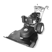
Removing the Stone Guard Flap - SPRINT
and PRO Models
NOTE: We turned the Trimmer on its side to take the photos in this section. To do so, we removed gas and oil from the machine. You
can access the underside of the Trimmer without having to drain the oil by tilting back on its handlebar. Tilting back with a full
Tank will probably cause the gas to leak and so draining the gas is still a good idea.
Before performing any maintenance procedure or inspection, stop the engine, wait five (5) minutes to allow all parts to cool.
Disconnect the spark plug wire, keeping it away from the spark plug.
Improper installation can cause damage to the trimmer bearings. Following
these directions carefully will protect your machine from damage.
Reassemble the components in the order shown in figure 31.
Figure 31
Backup Plate
(curve faces up)
Line Plate (6)
Line Plate
Standoff
Mow-Ball™
Support
Mow-Ball™
Support Bolt
Cutting Cord
Figure 30