24 DR
®
TRIMMER/MOWER
Tools needed:
3/8" Socket
7/16" Wrench
1/2" Wrench
1. Remove the Mow-Ball™ Support Assembly. See “Removing the Mow-Ball™
Support Assembly” on page 19.
2. Remove the Stone Guard Flap. See “Removing the Stone Guard Flap” on
page 20. This step is not applicable to the Self-Propelled model.
3. Remove the Bottom Shield. See “Bottom Shield” on page 21.
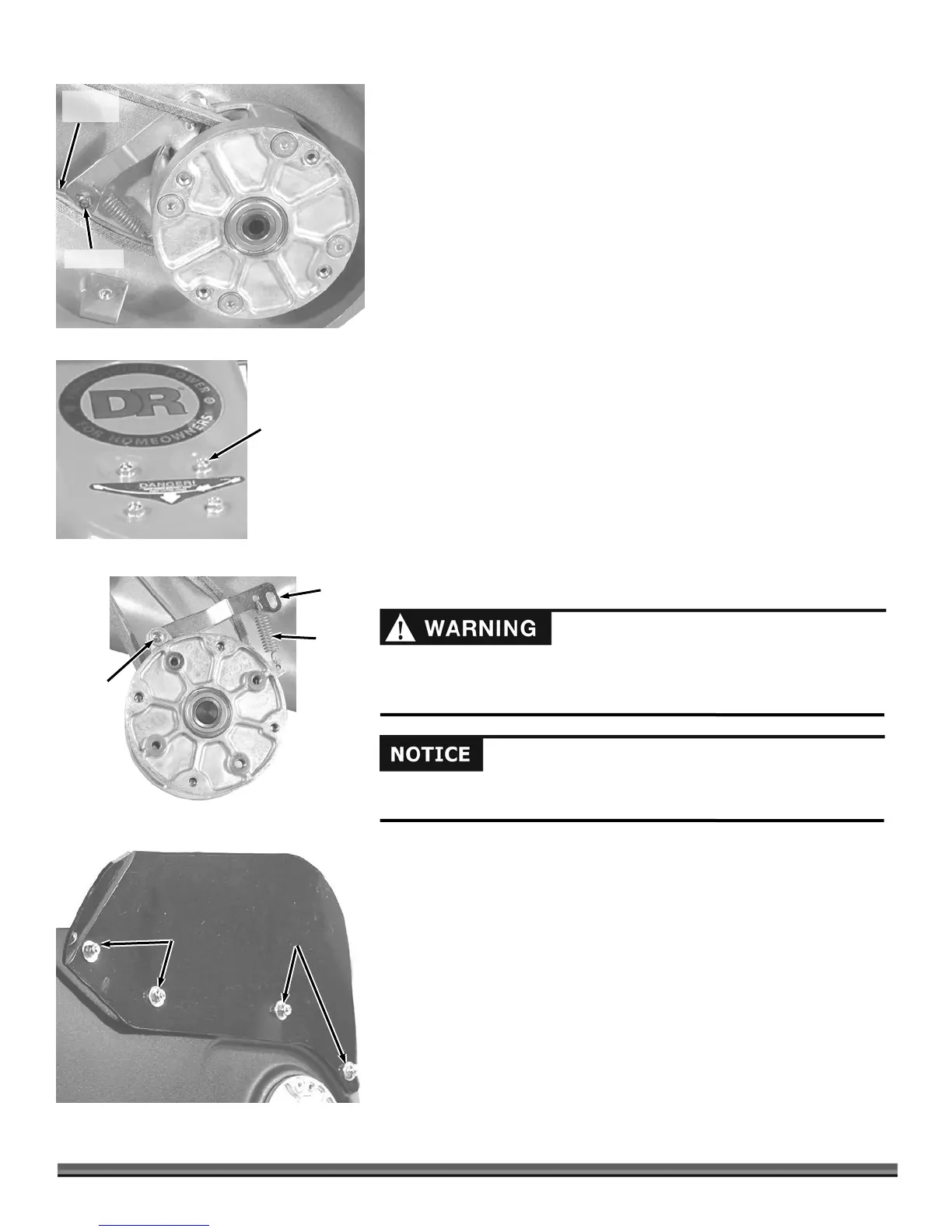
4. Using a 3/8" Socket, remove the Lock Nut from the Brake Actuator Rod and
remove the Rod from the Brake Arm (Figure 39).
5. Using a 1/2" Wrench, remove the four (4) Mounting Bolts that retain the
Bearing Housing from topside of the Trimmer Housing (Figure 40).
6. Turn the Bearing Assembly over to expose the Brake Arm Assembly and
unhook the Tension Spring from the Brake Arm (Figure 41).
7. Remove the Phillips Screw (Figure 41) retaining the Brake Arm.
8. Install the new Brake Arm Assembly in the reverse order.
NOTE:
When replacing the Brake Actuator Rod, do not tighten the Nut against the
Brake Arm. Leave the Nut just loose enough to allow the Rod to slide freely in the
Brake Arm slot.
Side Shield - All models
Tools needed:
3/8" Wrench
7/16" Wrench
1. Using a 3/8" Wrench or Socket (topside) and a 7/16" Wrench or Socket
(underneath), remove the four mounting Bolts, Nuts and Washers that
retain the Side Shield (Figure 42) and discard the old Shield.
2. Install the new Shield and secure in place with the mounting hardware.
You should never operate the trimmer without the side shield in place.
Always replace a damaged side shield immediately.
Before performing any adjustment, maintenance procedure or inspection,
stop the engine, wait five (5) minutes to allow parts to cool and disconnect
the spark plug wire, keeping it away from the spark plug.
Actuator
Ro
Lock Nut
Figure 39
Bearing Housing
Mounting Bolt
4PLS
Figure 40
Spring
Brake
rm
Phillips
Screw
Figure 41
Bottom Shield
Side Shield
Hardware to remove
Figure 42