CONTACT US AT www.DRpower.com 9
Figure 9
Product
Literature
(owners
manual,
engine
manual, etc.)
Trimmer
Head Locking
Tool
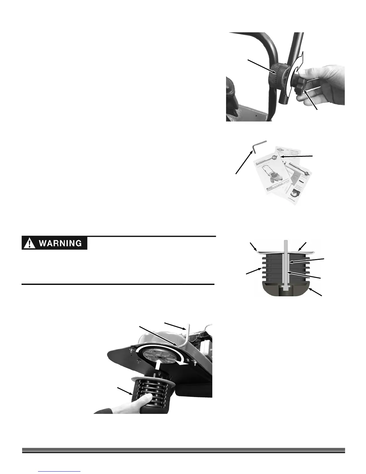
15. Lift the Upper Handlebar until it is near the operator position and tighten
the Handlebar Adjuster Knobs (Figure 8) (see the Safety & Operating
Instructions manual for more handlebar adjustment details).
NOTE: Ensure that the teeth of the Handlebar Adjuster mesh correctly as you
tighten the Knobs.
16. Open the Product Package and remove the Trimmer Head Locking Tool and
literature (Figure 9).
17. Remove the Mow-Ball Assembly from it’s packaging and make sure the
parts are assembled in the correct order and orientation (Figure 10).
18. Insert the Head Locking Tool that came in the Product Pack into the hole in
the nose of the Frame (Figure 11).
19. Looking down at the top of the Frame, thread the Mow-Ball™ Assembly
counterclockwise until the tool slides into a second hole in the shaft,
locking the Shaft so you can continue to screw on the Mow-Ball™ Assembly
until hand tight.
NOTE: If the Mow-Ball™ Assembly continues to turn, but does not tighten, check
to be sure that you locked the Head Locking Tool into the shaft.
20. Remove the Head Locking Tool after you have tightened the Mow-Ball™
Support Assembly.
Do not throw away your Trimmer packaging materials. Store the shipping box
and all inserts in a dry, safe area for future use. If there are any questions
contact us at www.DRpower.com or call 1-800-DR-OWNER (376-9637).
Mow-Ball™
Assembly
Figure 11
Head Locking
Tool
Hole in
Frame Nose
Tighten
Six Line
Plates
Figure 10
Spacer
Bolt
Mow-Ball™
Back-up
Plate
Outer Lip
Facing Up
Handlebar
Adjusting Knob
Figure 8
Meshing
Teeth
Be sure to fill the engine with oil and gas before use. If you start the engine
without oil in the crankcase, you will damage the engine beyond repair and the
warranty will not cover this damage. See the next section for adding oil and
gas.