8 DR
®
TRIMMER/MOWER
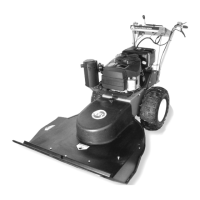
Figure 7
Wheel (left side shown)
Locknut
Axle
Black mark
on Inside of
Hub (Red
mark on
Right side
wheel)
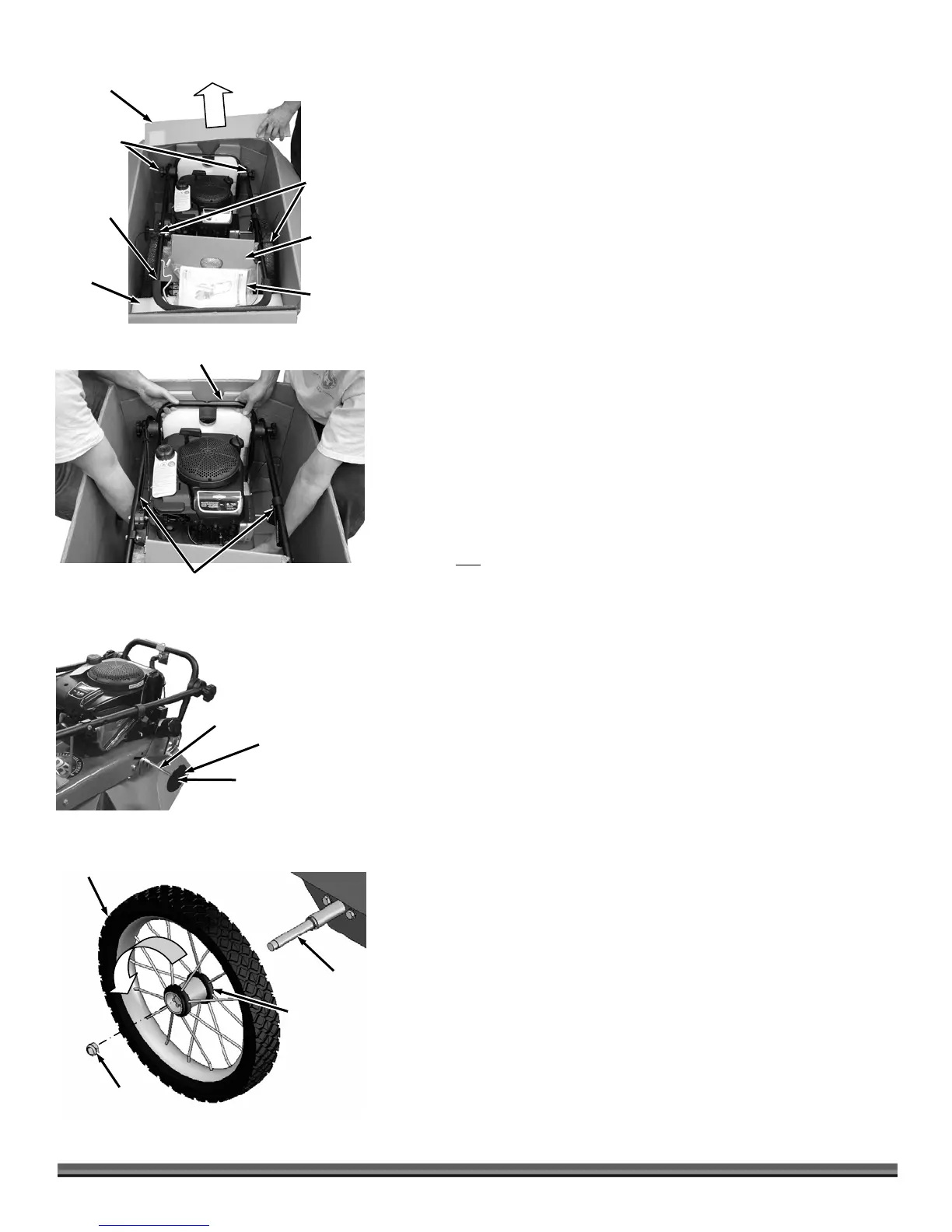
3. Use Wire Cutters to cut the Cable Ties that attach the Wheels to the
Handlebar and the Cable Tie that secures the Handlebar to the Box (Figure
4).
4. Remove the Wheels, Product Package and Top Rear Insert from the
Shipping Box.
5. Loosen the Handlebar Adjusting Knobs and rotate the Handlebar up
enough to remove the Frame Nose Insert and Mow-Ball™ Package.
6. Lower the Handlebar back down.
NOTE: Do not lift on the Upper Handlebar. Lift from the Lower Handlebar and
bottom of the machine.
7. With help from another person, lift the Trimmer from the Shipping Box
(Figure 5).
8. Position the Trimmer on the end of the Box or have someone position it on
the ground so you have access to the ends of the Axle (Figure 6).
Tip: Do not rotate the Shipping Caps off. Pull them from side to side so the nut
stays on the Axle.
9. Remove the Caps and Locknuts from both ends of the Axle.
NOTE: The right and left side of the machine is referenced from the Operating
position.
10. For the non
self-propelled Trimmer, slide the Wheels onto the Axle and go
to step 13.
NOTE: On the self-propelled Trimmer the right side wheel has a red mark and will
face in toward the Trimmer Body. The left side wheel has a Black mark and will face
in toward the Trimmer Body.
11. For the self-propelled Trimmer, install the left side wheel onto the Axle by
rotating it counter-clockwise as you slide it onto the Axle (Figure 7).
NOTE: A plastic plug will come out of the Wheels as you slide them on. Save this
plug to insert back into the Wheels if they need to be removed in the future.
12. Install the right side wheel onto the Axle by rotating it clockwise as you slide
it onto the Axle.
13. Secure the Wheels with the two Locknuts using a 5/8" Wrench.
14. If it’s not already there, place the Trimmer onto the ground.
Do Not Lift on
Upper Handlebar
Figure 5
Lower Handlebar
Figure 4
Product
Package
Frame Nose
Insert
Mow-
Ball™
Package
Wheel
Cable Ties
Handlebar
Hand Knobs
Top Rear
Insert
Handleba
Shipping Cap
Figure 6
Locknut (under cap)
xle