10
● To avoid false alarms, the alarm activation at the central device is to be locked.
● Supply the system with power. The gas transmitter runs an internal self-test during which
the status indicator's lights flash alternately for a short time. During this running-in peri-
od, the green status indication is on and the yellow status indication flashes. Operation
then subsequently begins using the configuration set on delivery. We recommend that
the factory calibration and configuration are checked. (Due to national regulations, it may
be necessary to run a calibration of the zero point and the sensitivity.)
● Unlock the alarm activation at the central device to put the system back to normal oper-
ating mode.
Safety Integrity Level
– The gas transmitter is suitable for use in SIL 2 applications.
Measuring mode
The gas transmitter generates a 4 to 20 mA signal, proportional to the measured gas con-
centration, when the gas transmitter is configured for analogue signal transmission.
Maintenance
Maintenance intervals
Observe EN 50073 and respective national regulations.
Daily
● Visual inspection to determine readiness for operation – the green status indication lights
up.
While commissioning
● During the automatic self-test, check the function of the yellow and green status indica-
tion.
● Check zero calibration.
● Check the current interface and if required also the HART communication.
At regular intervals, which are to be determined by the person responsible for the gas
warning system – recommendation, 6 months:
● Check the zero point and the span calibration.
● Check signal transmission to central unit and alarm activation.
● A calibration interval of more than 6 months is possible under the following conditions: Af-
ter an action time of a maximum of six months, a check should be made of whether an ob-
struction can occur in the gas entrance to the measuring cuvette within the given
application, e.g. due to dust, oil etc. If a restriction to the function caused by these effects
is excluded then the calibration interval can be prolonged – recommendation: maximum
24 months.
NOTICE: For applications with Safety Integrity Level (SIL) and any other configu-
ration (when applicable), observe the technical handbook.
Current Meaning Configurable
(0.7...3.6 mA)
4 mA Zero – – –
20 mA Full-scale deflection – – –
<1.2 mA Fault, non-latching Yes
3.8 mA ... 4 mA Under-range – – –
20 mA ... 20.5 mA Full-scale deflection exceeded (over-range) – – –
>21 mA Defect in the analogue interface – – –
3 mA Maintenance signal Yes
2 mA Beam block warning (preventive maintenance func-
tion)
Yes
<1.2 mA
Device in multidrop operation (polling address 1 ... 15)
– – –
Yearly
● Inspection by competent personnel. The inspection intervals are to be individually deter-
mined with regard to safety regulations, process control conditions and device-related
requirements.
Check the measuring cuvette of the gas transmitter and clean if required
● To avoid false alarms during inspection, set the analogue output signal to maintenance
signal or ensure that the alarm activation at the central device is locked.
● Remove the splash guard and, when required, any additional accessories from the gas
transmitter.
● Examine the air inlet and air outlet openings for dirt and damage.
● Examine the windows and mirrors, as well as additional accessories for dirt, clean with
water or alcohol and dry using cotton wool or a cloth. Do not scratch the mirrors or win-
dows!
● Attach the splash guard and when required any other accessories to the gas transmitter.
● Re-activate the analogue output signal if it has been set to maintenance signal. Or, un-
lock the alarm activation at the central device.
Calibration
The calibration can be carried out using the magnetic wand (45 43 428) directly at the gas
transmitter.
Zero-point calibration Dräger PIR 7000 / Dräger PIR 7200
Attention: Always first calibrate the zero point before the sensitivity.
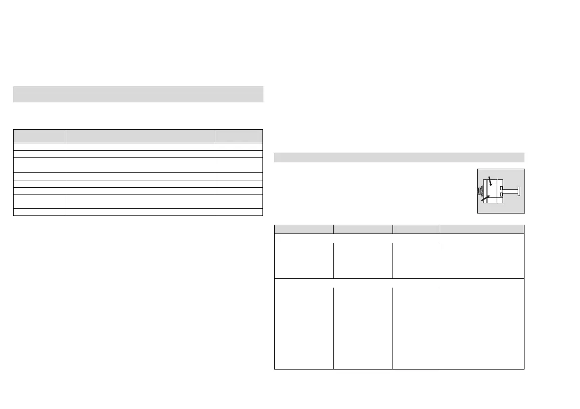
Handling the magnetic wand:
The gas transmitter contains two contact locations marked by » 0 « and
» S « on the housing. To calibrate, place the magnetic wand on the
contact locations.
Action Status Indicator Output Signal Meaning
Prepare the device for zero calibration:
Place the magnetic
wand on the mark
» 0 «.
Green/yellow flash
alternately and
quickly
Measuring
mode
Unlock device for zero cali-
bration.
Remove the mag-
netic wand.
Green and yellow are
on
Measuring
mode
Device waits for the start of
calibration.
Initiate the zero calibration:
Place the magnetic
wand within 2 sec-
onds on marking
» 0 « for at least
1 second and then
remove it.
Green/yellow
flashes alternately
Maintenance
signal
The calibration routine is
started.
Place on calibration
adapter PIR 7000.
Feed nitrogen or
synthetic air with at
least 0.5 L/min onto
the sensor.
00423885_01.eps
0
S