Installing and Commissioning the Dräger Polytron Pulsar 2
23
Step 1. Initial Receiver alignment
Select in the 'Rx Align + Zero' menu to put the Receiver into its Alignment Mode. Digital signals from the Receiver will in turn com-
mand the Transmitter to flash in its Alignment Mode (an irregular flash sequence) and cause the Handheld to show an Alignment screen.
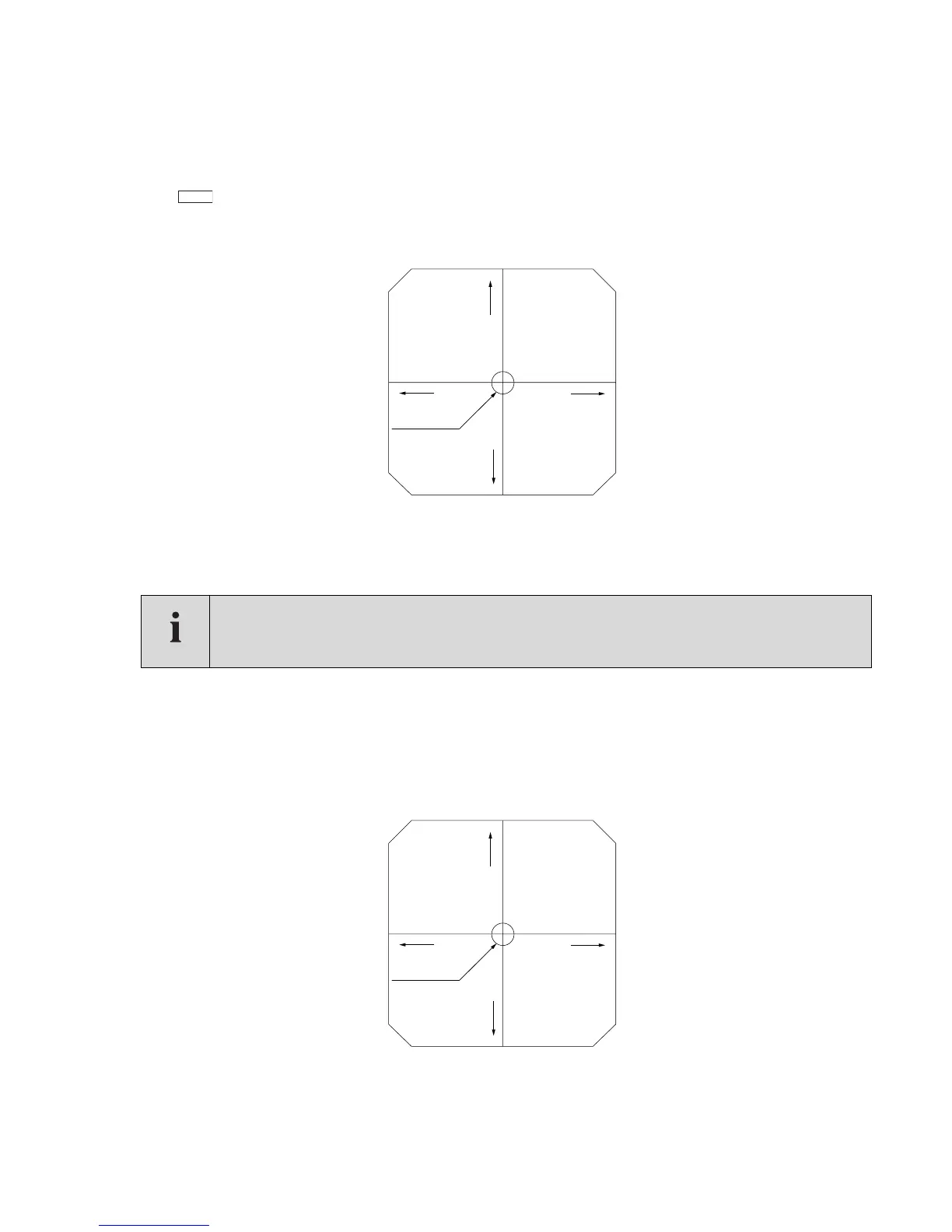
The live display shows the received signal strength both numerically and as a bar-graph. Above and to the right is a Cartesian 'target'
showing the orientation of the Receiver with respect to the straight line to the Transmitter lens:
First move the Receiver around to be sure you have found the strong central peak in signal. Now make slow adjustments in the vertical
and horizontal directions alternately, each time correcting the direction with the greater error, until the display looks like the diagram.
Tighten the eight screws progressively in rotation to avoid shifting the alignment.
Step 2. Transmitter alignment
4 to 60m Transmitter
Connect the Handheld and check that the signals from the Receiver are being displayed. If they were absent it would indicate that the dig-
ital link from the Receiver was not connected, usually due to a wiring fault. Also look into the Transmitter lens to check it is flashing at the
correct, irregular rate of four per second. A regular twice per second would indicate inadequate voltage at the supply or excessive voltage
drop in the supply cables.
At the left of the Alignment screen the Transmitter 'target' shows its orientation with respect to the straight line to the Receiver lens:
First move the Transmitter around to be sure you have found the strong central peak in signal. Make slow adjustments as before, correct-
ing the horizontal or vertical direction with the greater error, until the display looks like the diagram. Tighten the eight screws progressively
in rotation to avoid losing the alignment. The Transmitter and connector covers can now be replaced. Proceed to step 3.
NOTE
The alignment screen on the Draeger handheld terminal will vary depending on whether you are aligning a 4-
60m Transmitter or the longer range Transmitters (30-120m and 100-200m). Please ensure you follow the
correct step for EITHER a 4-60m Transmitter or 30-120m and 100-200m Transmitters highlighted below.
ALIG
LENS
UP
Correctly
Aligned
LENS
DOWN
LENS RIGHTLENS LEFT
01423892.eps
LENS
UP
Correctly
Aligned
LENS
DOWN
LENS RIGHTLENS LEFT
01523892.eps