10
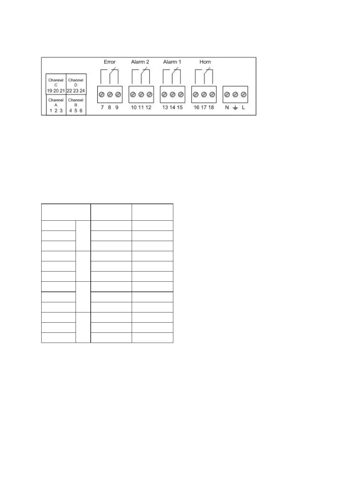
Connection diagram Dräger RailGard-W4 and -W1
All relays shown are in a de-energised position, when the unit is switched-off !
The Fault relay as well as the Alarm 1 and Alarm 2 relays are normally energised.
Terminals for sensor connection:
Terminal with short-
circuit straps
with
converter
1 +24V brown
2 4-20mA yellow
3
Channel A
GND black
4 +24V brown
5 4-20mA yellow
6
Channel B
GND black
19 +24V brown
20 4-20mA yellow
21
Channel C
GND black
22 +24V brown
23 4-20mA yellow
24
Channel D
GND black
Note:
Only channel A can be equipped with a converter in the Dräger RailGard-W1.
Dräger RailGard-W4 allows to connect the converter from channel A to D.
 Loading...