23
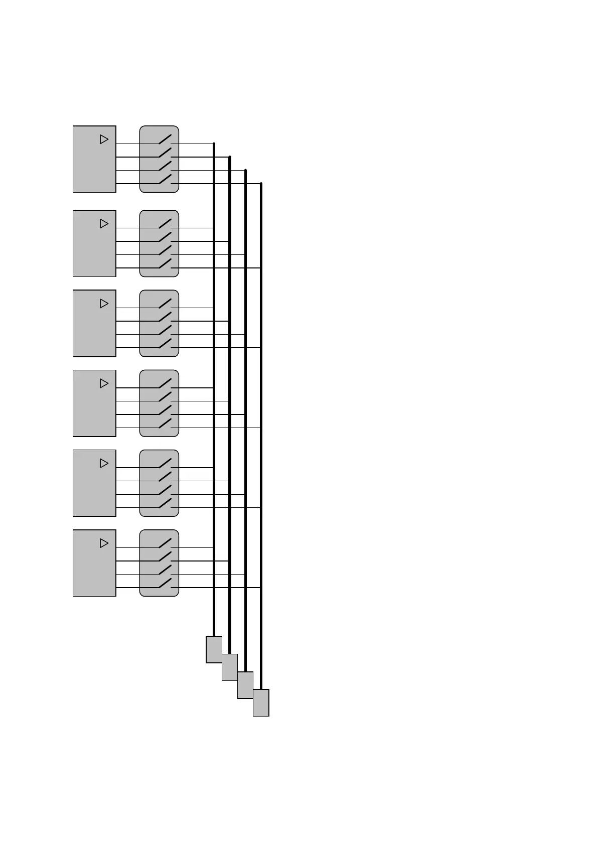
7.9. Circuit diagram for configuration of the output relays and association of
channels
Description of the configuration and
association:
The output relays can be assoiated via
switches A1 to A4 to the levels (alarm
thresholds) 1 to 4 of channels A to F (see
page 22).
This results into the following possible
combinations:
1 Alarm threshold
6 sensors 4 alarm groups
2 Alarm thresholds
6 sensors 2 alarm groups
3 Alarm thresholds
6 sensors 1 alarm group
4 Alarm thresholds
6 sensors 1 alarm group
Level 1
Level 2
Level 3
Level 4
A
Level 1
Level 2
Level 3
Level 4
B
Level 1
Level 2
Level 3
Level 4
C
Level 1
Level 2
Level 3
Level 4
D
Level 1
Level 2
Level 3
Level 4
E
Level 1
Level 2
Level 3
Level 4
F
A1
A2
A3
A4
A1
A2
A3
A4
A1
A2
A3
A4
A1
A2
A3
A4
A1
A2
A3
A4
A1
A2
A3
A4
R
1
R
R
R
2
3
4
 Loading...