14
2. Adjusting the zero point
• Apply zero gas (e.g. 99.99 % by Vol. N
2
) to the sensor, which corresponds
to ZERO (4 mA).
• The output current can be checked with a voltmeter at the two test points
on the left hand side of the converter (“Measuring Point 4-20mA”).
Alternatively you may refer to the display of the Dräger RailGard, provided
that the corresponding channel configured correctly.
• Use the potentiometer ("Adjust sensor zero point") to adjust the voltage at
the test point to 0.4 V (indication on the voltmeter).
• The display of the Dräger RailGard shall indicate "0".
3. Adjusting the span
• Apply span gas (e.g. 50 %LEL) to the sensor.
• The output current can be checked with a voltmeter at the two test points
on the left hand side of the converter (“Measuring Point 4-20mA”).
Alternatively you may refer to the display of the Dräger RailGard, provided
that the corresponding channel configured correctly.
• Use the potentiometer ("Adjust sensor sensitivity") to adjust the output
current to the value which corresponds to the span gas being used.
• If a 50 %LEL reference gas is used, the display on the Dräger RailGard
shall indicates "50"; the voltmeter should indicate 1.2 V (corresponding to
12 mA).
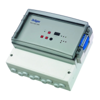
Potentiometers and test points at the converter
 Loading...