7
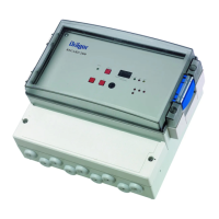
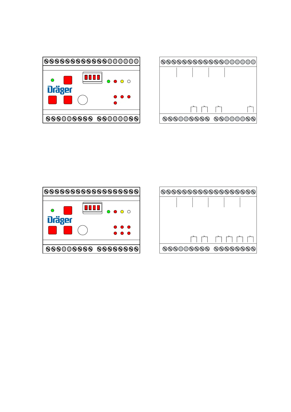
Connection diagram Dräger RailGard-S4
All relays shown are in a de-energised position, when the unit is switched-off !
The Fault relay as well as the Alarm 1 and Alarm 2 relays are normally energised.
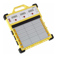
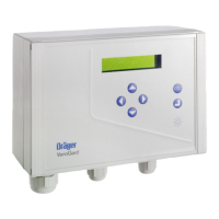
Connection diagram Dräger RailGard-S6
All relays shown are in a de-energised position, when the unit is switched-off !
The Fault relay as well as the Alarm 1 and Alarm 2 relays are normally energised.
117
RS232
Power Reset
Channel A B C D E F
Concentration
F1 F2
x10 Error L
A
Hu
BC
DEF
A1
A2
A3
A4
18
35
RailGard-S6
117
RS232
Power Reset
Channel A B C D
Concentration
F1 F2
x10 Error L
A
Hu
BC
D
A1
A2
18
35
RailGard-S4
18 35
117
+ S –
+ – NC
Channel A
+ S –
Channel B
+ S –
Channel C
+ S –
Channel D
Power supply
Error
Alarm 1
Alarm 2
24 V DC
Horn
18 35
117
+ S –
+ – NC
Channel A
+ S –
Channel B
+ S –
Channel C
+ S –
Channel D
+ S –
Channel E
+ S –
Channel F
Power supply
Error
Alarm 1
Alarm 2
24 V DC
Alarm 3
Alarm 4
Horn
 Loading...