LT-2334
17
SERVICING AND COMPONENT REPLACEMENT
POC SERVICING AND COMPONENT
REPLACEMENT
The 125 series POC requires no routine maintenance or servicing and there
is no specic testing required. However oxygen concentration and inspiratory
trigger sensitivity can be checked if necessary. See page 19 for instructions
on testing O
2
% and trigger sensitivity.
There are a limited number of components that are serviceable or
replaceable in the eld. This section includes step-by-step instructions for
removal and replacement of these components.
Tools and Equipment Needed:
• T-10 Torx driver
• 5/16” Hollow core socket
• Oxygen analyzer
• Narrow bladed at head screwdriver
Cover
To remove and replace cover:
1. Ensure that all power is removed from the unit including battery.
2. Lay the POC on its side with the battery cavity to the right side and the
USB port facing upward.
3. Using a T-10 torx screwdriver remove the 6 screws securing the cover.
Cover/Case
T-10 Torx
Screwdriver
4. Carefully lift the cover off the unit and place it aside.
5. Replace the cover by placing it on top of the unit and secure with 6
screws (torque to 7 in-lbs).
Control Panel Label
To remove and replace control panel label:
1. Ensure that all power is removed from the unit including battery.
2. Remove cover from unit.
3. Disconnect the silicone oxygen tubing from the back of the oxygen
outlet port.
Disconnect Tubing from Oxygen Outlet Port
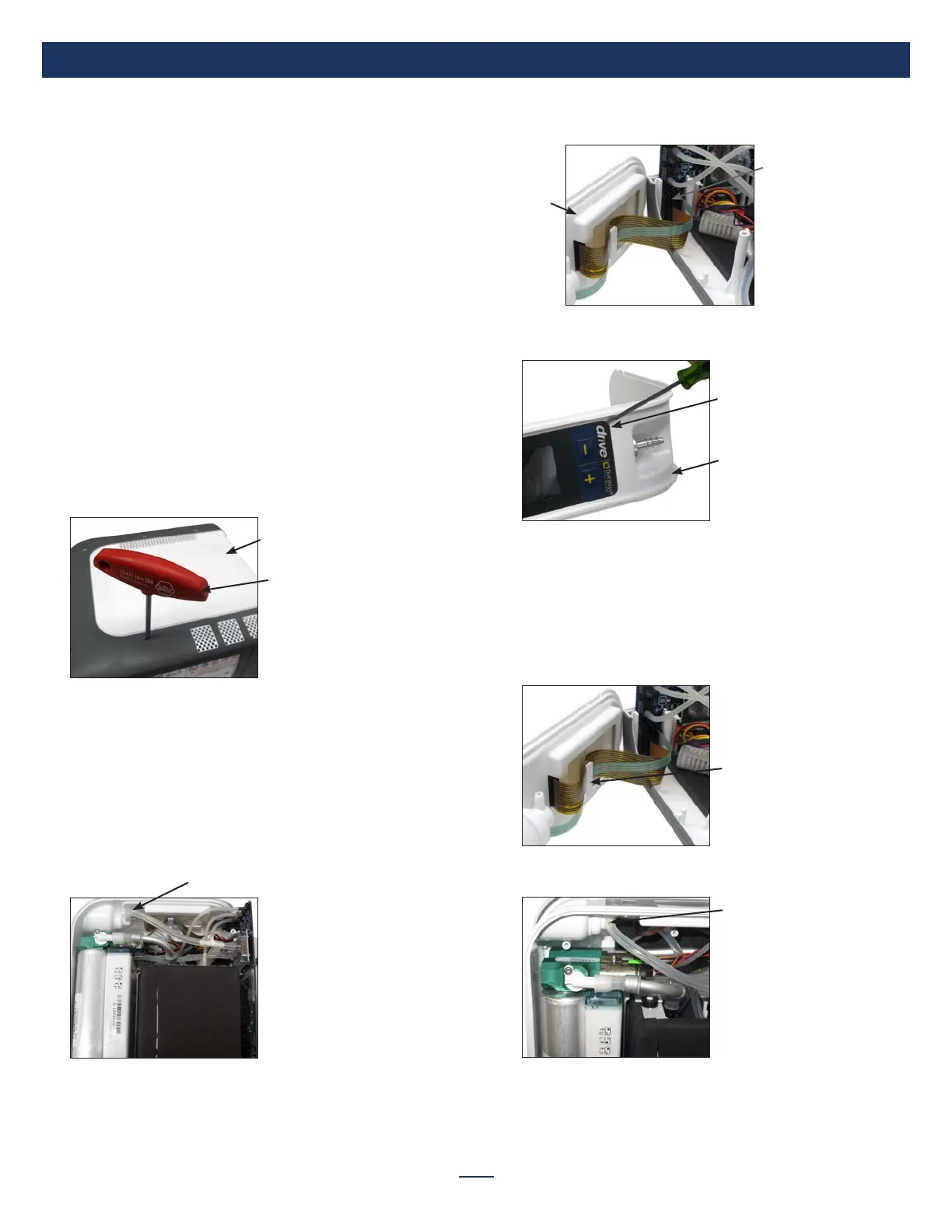
4. Lift cover plate up and out of case. Place it beside unit.
5. Disconnect both the keypad (green) and LCD display (gold) ribbon
connectors from the pc board.
Cover
Plate
Disconnect Ribbon
Connector
6. Loosen control panel label with a small instrument such as a narrow
bladed at head screwdriver and remove from cover plate.
Cover Plate
Loosen Label
7. Remove backing and any back lm from the new control panel label.
8. Slide the end of the ribbon connector through the hole in the cover
plate.
9. Align the label and seat it into place on the cover plate on top of the
LCD display.
10. Attach both the keypad and LCD display ribbon connectors to the pc
board.
11. Secure ribbons using plate restraint.
Cover Plate Restraint
12. Position cover plate in case.
13. Re-attach the silicone oxygen tubing to the back of the oxygen port.
Re-attach Tubing
14. Replace cover.