VF61 Programming Chart
Model VF61 ___________________ SN: _______________________
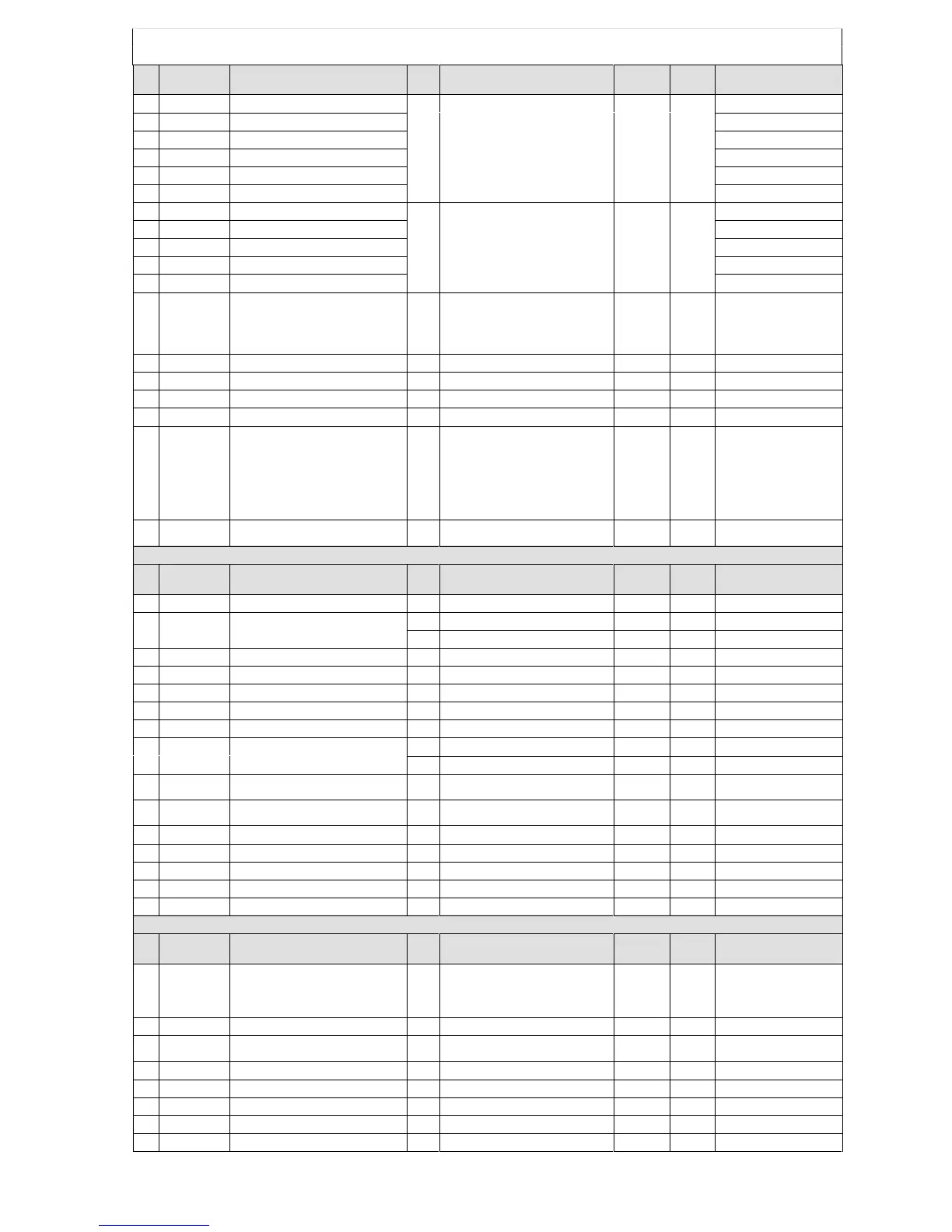
Code
No.
Function Abbrev.
Function setting item
Unit
Setting range (Setting Resolution)
Change
during
operation
Default
User
value
80 Acc2.Time Acceleration (2) time
Sec. .1 to 3600 Impossible 30 Sec
81 Dec2.time Deceleration (2) time
82 Acc3.Time Acceleration (3) time
83 Dec3.Time Deceleration (3) time
84 Acc4.Time Acceleration (4) time
85 Dec4.Time Deceleration (4) time
86 Preset3.F Preset (3) frequency
Hz -Top.F to +Top.F Possible 0 Hz
87 Preset4.F Preset (4) frequency
88 Preset5.F Preset (5) frequency
89 Preset6.F Preset (6) frequency
90 Preset7.F Preset (7) frequency
91 Term-9.Sel
Terminal 9 (multifunction analog output)
selection
N/A
Vout Output voltage (a)
Iout Output current (b)
Torq Torque
current(c)
Fout Output frequency (d)
Internal Mon justing monitor for internal
use (e)
Possible
(b)
92 Carrier.F Carrier frequency kHz
4 to 15
Possible 15 kHz
93 L-SP.Adjust Line speed indication adjustment N/A
0 to 3200
Possible 0
94 STB.Adjust STB adjustment %
0 to 100
Possible 0%
95 OL.Pre-Alarm Overload pre-alarm setting % 0 to 100 Possible 50%
96 LED-Disp.Sel Inverter LED indication item selection N/A
Fout Output frequency (a)
Fref Reference frequency (b)
Iout Output current (c)
Vout Output voltage (d)
Torq out Torque current (e)
Vdc DC voltage (f)
Motor Speed Synchronous motor RPM (g)
OL counter Overload counter (h)
Line Speed Line Speed (i)
ROM Version ROM Version
(j)
Possible (a)
97 ALM-data cir Fault history clear N/A
yes (a)
no (b)
Impossible (b)
Code group special settings
Code
No.
Function Abbrev. Function setting item Unit Setting range (Setting Resolution)
Change
during
operation
Default User Value
17 Motor.Cap Rated motor capacity kW .4 to rated inverter capacity Impossible N/A
18 Motor.V Rated motor voltage
V (400V class) 320 to 480 Impossible 400V
V (200V class) 160 to 240 Impossible 200V
19 Motor.I Rated motor current A 1 to Rated inverter current Impossible N/A
20 Motor.F Rated motor frequency Hz 30 to 400 Impossible 60Hz
21 Motor.RPM Rated motor RPM rpm 300 to 24000 Impossible 1740rpm
22 Motor.Pole Number of poles of the motor
N/A
2,4,6,8 (pole) Impossible N/A
23 Motor.R1drop Primary resistance drop of the motor % 0 to 25 Impossible 5%
24 DB.V Dynamic Brake operating voltage
V (400V class) 540 to 740 Possible 720V
V (200V class) 270 to 370 Possible 360V
25 0 to 10V Gain
Frequency setting input + side (0V to
10V) gain
% 50 to 150 Possible 100%
26 -10 to 0V Gain
Frequency setting input - side (-10V to
0V) gain
% 50 to 150 Possible 100%
27 Term-9.Gain
Terminal 9 (analog output) gain
% 50 to 150 Possible 100%
28 Term-9.Ofset
Terminal 9 (analog output) offset
% -5 to +5 Possible 0%
29 VDC.DET.Gain
DC voltage detection gain
% 90 to 110 Possible 100%
30 CRT.DET.Gain
Output current detection gain
% 50 to 150 Possible 100%
31 FCL.Level
FCL level
% 80 to 100 Possible 100%
Special Setting 2 (Sp.set-2)
Code
No.
Function Abbrev. Function setting item Unit Setting range (Setting Resolution)
Change
during
operation
Default User Value
17 4 to 20 out.Sel 4 to 20 mA output selection N/A
Vout Output voltage (a)
Iout Output current (b)
Torq Torque current (c)
Fout Output frequency (d)
Internal Mon Adjustment monitor for internal
use (e)
Possible (b)
18 4 to 20 out.gain 4 to 20 mA output gain % 50 to 150 Possible 100%
19
4 to 20
out.Ofset
4 to 20 mA output offset % -1 to +1 Possible 0%
20 ISOin.Gain Insulated input gain % 50 to 150 Possible 100%
21 ISOin.Ofset Insulated input offset % -1 to +1 Possible 0%
22 PG-Pulse Number of PG pulses P/R 100 to 2400 Impossible 600 P/R
23 ASR.P-Gain ASR proportional gain N/A 1 to 200 Possible 5
24 ASR.I-Time ASR integral time mS .20 to 200 Possible 10 mS
-24-