3/29
STEP 1
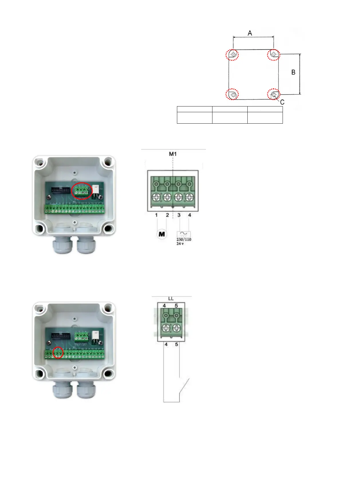
– Install and fix VIP5 Controller
The VIP5 Controller should be fixed using the 4 fixing holes.
For further information, refer to Section 4 of this manual.
STEP 2
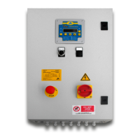
– Connect power input and pump (or control solenoid) output to the VIP5 connector strip “M1”
Further details in section 5
STEP 3
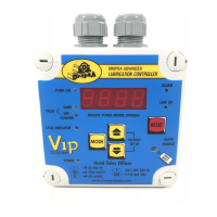
– Connect the pump low level switch to pin 4 and 5 on connector strip “M2”
For complex connections involving
4..20mA please refer to section 5
If you do not have an end of cycle switch
(the controller will operate in timer only
mode) then skip to step 5