9.2.1 Burner
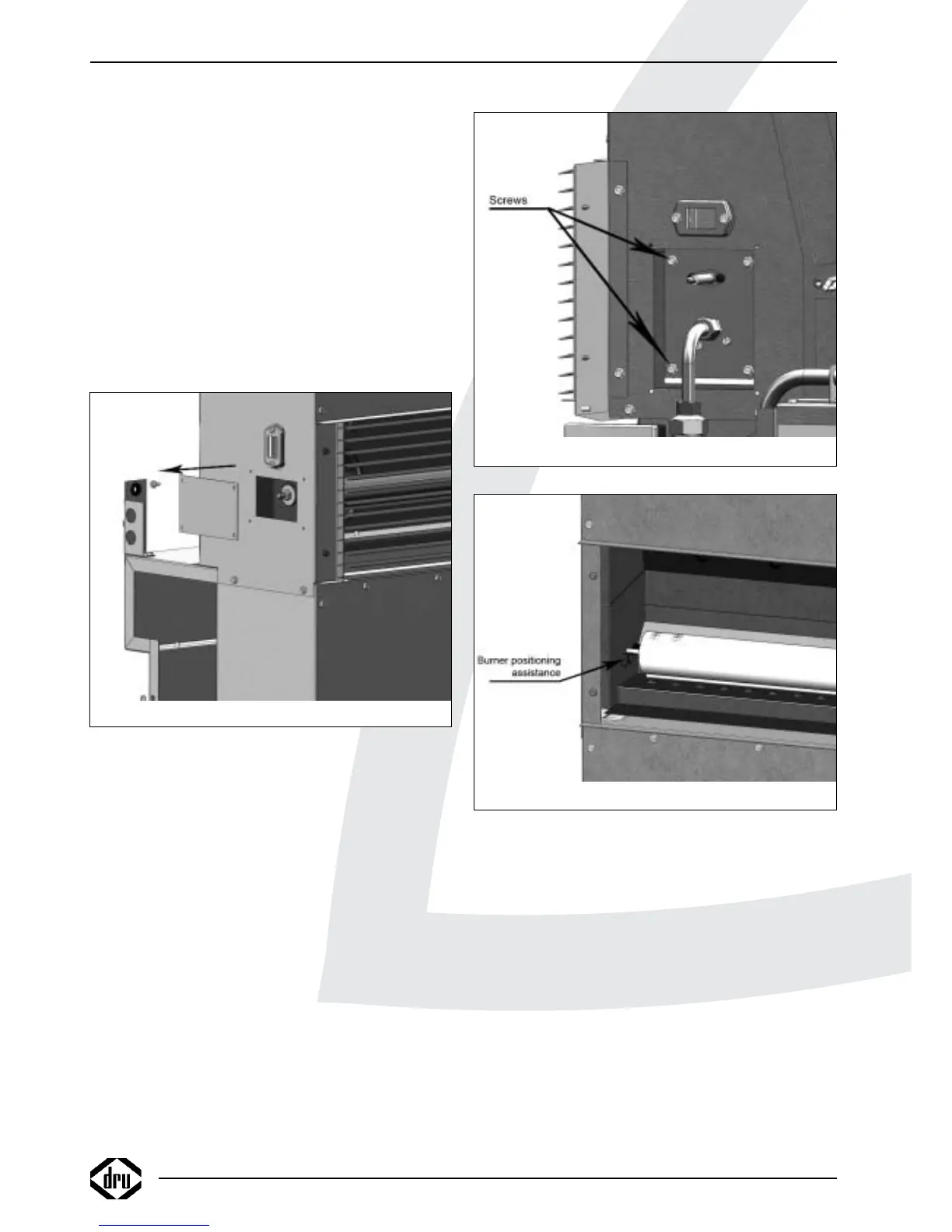
!Caution Only for Power Flue 7kW
- Remove the cover plate to the left on the
convection housing; see fig. 12;
- Unscrew the nut;
- Remove the washer and the sealing ring.
For all appliances, continue as described below:
• Remove the ignition cap.
• Remove the sealing surrounding the electrode pen.
• Take out the 4 screws of the cover plates around the gas
tube and the ignition pen (see fig. 9).
• Remove the cover plates.
• Unscrew the brass union of the gas tube under the
ignition pen.
• Unscrew the brass union of the gas tube on the gas
control valve.
!Caution Make sure the thread reducing bushes on the
gas control valve do not rotate as well.
• Remove the gas tube from the appliance.
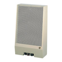
• Take out the 4 screws of the burner; see fig 13.
• Carefully remove the burner tube from the combustion
chamber.
• Place the new burner in reverse order.
!Caution Only for Power Flue 12kW and 16 kW:
- Place the pin at the end of the burner tube
on the V; see fig. 14;
- Position the burner tube in such a way, that
the pin drops in the hole.
• Check supply pressure.
• Check the burner pressure and, if necessary, adjust it as
described in section 7.2
9.2.2 Electrode pen
• Remove the ignition cap.
• Remove the sealing surrounding the electrode pen
• Take out the 4 screws of the cover plates around the gas
tube and the electrode pen (see fig. 9).
• Remove the cover plates.
• Take out the 2 screws of the mounting plate.
• Remove the electrode pen.
• Place the new electrode pen in reverse order
9.2.3 Automatic ignition sequence
• Take out the 2 screws of the cover on the automatic
ignition sequence (see fig. 15)
(the upper screw is used to fix the automatic burner to
the gas control valve; the lower screw fixes the cover)
• Remove the cover.
• Pull the 2 connectors out of the automatic ignition
sequence (see fig. 16).
INSTRUCTIONS FOR INSTALLATION
Fig. 12
Fig. 13
Fig. 14
14