• Pull out the ignition cable.
• Remove the automatic ignition sequence by pulling it to
the front side of the appliance.
• Place the new automatic ignition sequence in reverse
order.
!Caution - Place the automatic ignition sequence in such
a way, that the connector is connected again;
- Prevent wiring from getting stuck under the
cover.
9.2.4 Gas control valve
• Remove the automatic ignition sequence, as described
above in section 9.2.3.
• Remove the ignition cap.
• Remove the sealing surrounding the electrode pen
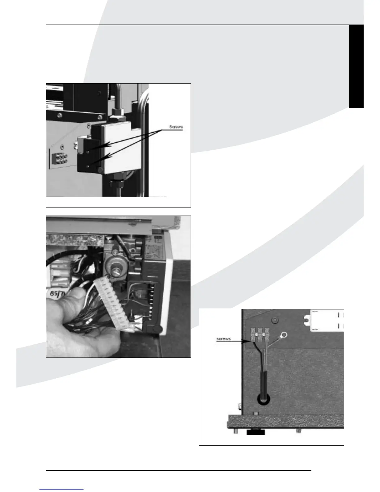
• Take out the 4 screws of the cover plates around the gas
tube and the electrode pen (see fig. 9).
• Remove the cover plates.
• Unscrew the brass union of the gas tube under the
electrode pen.
• Unscrew the brass union of the gas tube on the gas
control valve.
• Disconnect the earth wire.
• Remove the gas control valve.
• Disconnect the thread reducing bushes (top and bottom
side) from the gas control valve.
• Connect the thread reducing bushes to the new gas
control valve.
!Caution Use new sealing rings when mounting the
thread reducing bushes.
• Place the gas control valve in opposite order.
• Adjust the burner pressure as described in section 7.2
• Perform a final check as described in chapter 7
9.2.5 Convection fan
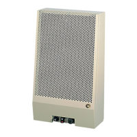
• On the appliance, disconnect the electric wiring of the
convection fan (see fig. 17).
• Take out the screws from the lower cover plate at the
front of the appliance.
• Remove this plate.
• Remove the electric cable from the cable clips.
• Take out the 4 socket cap screws that are used to mount
the fan (see fig. 18).
• Remove the fan.
• Place the new fan in reverse order
Kamara
INSTRUCTIONS FOR INSTALLATION
15
Fig. 15
Fig. 16
Fig. 17
English