9.2.6 Combustion fan
• Take out the clamp of the flexible flue gas discharge tube.
• Remove the flexible flue gas discharge tube.
• Take out the clamp that is used to mount the venturi tube
on the fan.
• Remove the venturi tube.
• Disconnect the air hose from the fan (positive measuring
point).
• Disconnect the electric wiring from the fan.
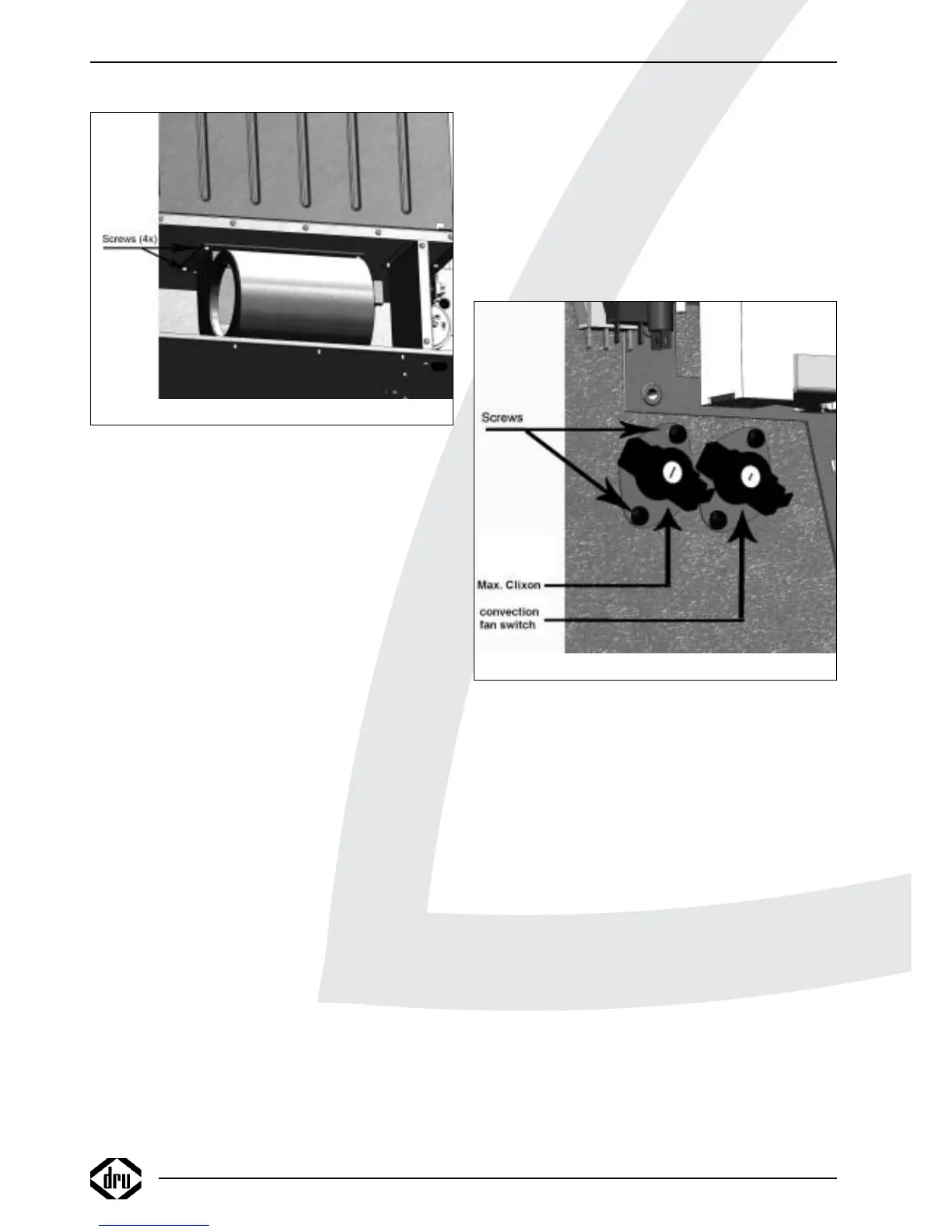
• Take out the 4 screws of the assembly plate (see fig. 6).
• Remove the fan assembly.
• Take out the 3 screws connecting the fan to the assembly
plate.
• Remove the fan
• Place the new fan in reverse order.
!Caution - Using new gaskets;
- Fix the venturi tube using heat-resistant
sealant and the clamp;
- Also fix the flexible discharge tube using the
sealant and the clamp;
- Make sure that the wiring is lying free from
the convection box and the fan house.
9.2.7 Temperature limit switch
(maximum thermostat)
• Disconnect the fast-on connections of the electrical
connection.
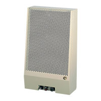
• Take out the 2 screws of the mounting plate (see fig. 19 of
Power Flue 12/16kW).
!Tip Only for Power Flue 7kW:
- Take out the 2 screws on the control panel
(see fig. 11);
- Slightly lift the panel;
- Take out the upper screw of the mounting
plate.
• Remove the switch.
• Place the new switch in reverse order.
!Caution For the Power Flue 16kW, 2 distance bushes
and a gasket are used.
9.2.8 Convection fan switch
• Disconnect the fast-on connections of the electrical
connection.
• Take out the 2 screws on the mounting plate (see fig. 19);
!Tip Only for Power Flue 7kW:
- Take out the 2 screws on the control panel
(see fig. 11);
- Slightly lift the panel;
- Take out the upper screw of the mounting
plate.
• Remove the switch.
• Place the new switch in reverse order.
9.2.9 Thermostat
• Take out the 2 screws on the control panel (see fig. 11).
• Slightly lift the control panel.
• Remove the thermostat.
• Disconnect the wiring.
• Place the new thermostat in reverse order.
INSTRUCTIONS FOR INSTALLATION
16
Fig. 18
Fig. 19