Copyright 2010 Baker Hughes Company.
English–PACE Indicators Instruction Manual | 55
Installation and Ancillary Equipment Kit
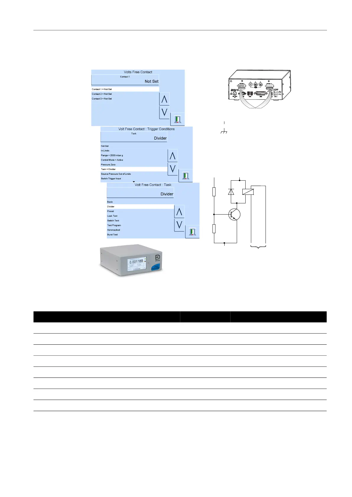
6.9.3 Volts-free Contact Option
The Volts-free Contact option provides a selectable relay contact toggle depending on conditions
set in the PACE instrument.
6.10 Installation and Ancillary Equipment Kit
Refer to the Data Sheet for details.
Table 6-6: Pin Number and Function
Pin Number Function Pin Number Function
1 Relay 1 normally CLOSED 9 Relay 3 common
2 Relay 1 normally OPEN 10 0V return
3 Relay 1 common 11 +24 V dc output, 100 mA max
4 Relay 2 normally CLOSED 12 Switch Input 1
5 Relay 2 normally OPEN 13 Switch Input 2
6 Relay 2 common 14 (not used)
7 Relay 3 normally CLOSED 15 (not used)
8 Relay 3 normally OPEN
Each selection has
three Volts-free
Contacts.
Selection of trigger
conditions.
Selection of trigger
conditions.
30V maximum with respect to
chassis.
Rated output = 24V
30Vmax
To maintain PACE product safety, external circuits
connected to the instrument must meet Safety
Extra-Low Voltage (SELV) requirements.
0V
+V
event
trigger
24 Vdc maximum
30 Vdc wrt chassis
1 A resistive maximum
Typical Volts-free
schematic
Relay contacts rated at 30 Vdc, 1 A resistive,
200 mA inductive.
22V to 26V
ANALOGUE 1
ANALOGUE 2
15
CONSULTHANDBOOK
volts-free connections
 Loading...