Do you have a question about the Druck PACE1000 and is the answer not in the manual?
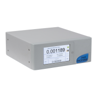
Overview of the PACE Pressure Indicator, its features, and remote operation capabilities.
Lists items included in the PACE1000 packaging.
Instructions for packing the instrument for storage or return.
Guidance on positioning the instrument and ensuring proper airflow.
Safety warnings and procedures for connecting pressure lines.
Details on various available pressure adaptors for the PACE instrument.
Specifies required thread types and sealing methods for pressure connections.
Procedures for connecting the Unit Under Test (UUT) pneumatically or hydraulically.
Steps for making pneumatic connections, including safety warnings.
Steps for making hydraulic connections, including safety precautions.
Information on rack-mount and panel-mount options for instrument installation.
Details the procedure for rack-mounting the instrument.
Details the procedure for panel-mounting the instrument.
Instructions for connecting the power supply and safety precautions.
Overview of rear panel communication ports and interfaces.
Details on connecting and configuring the RS-232 interface.
Instructions for connecting and configuring the IEEE 488 interface.
Procedure for connecting a single instrument via IEEE 488.
Procedure for connecting multiple instruments via IEEE 488.
Steps to prepare the instrument before operation.
Describes the instrument's power-up sequence and self-test.
Explains the instrument's measure mode and touch screen interface.
Details on the data logging function, including memory status and recall.
General guidance on operating the instrument and specific procedures.
Introduction to operating the instrument and connecting supplies.
Explains the instrument's measure mode and touch screen interface.
Explains the pre-determined functions and task selection for measurement.
Details the task for measuring leak rate over a specified dwell time.
Access to instrument settings for measure and control modes.
Overview of supervisor setup, calibration, and display settings.
Menu for changing settings, including PIN, alarms, and communications.
Accessing instrument status information like software and hardware build.
Provides read-only information on the current software installed in the instrument.
Overview of routine maintenance and component replacement procedures.
Instructions for inspecting the instrument for signs of damage or dirt.
Guidelines for cleaning the instrument's front panel.
Refers to the standard serviceability test procedure.
Step-by-step procedure for updating the PACE1000 internal software.
Details the self-test and diagnosis system of the PACE instrument.
Procedure to verify if the PACE is serviceable and check its functions.
Steps for testing the Ethernet connection and IP address.
Details the PACE open Ethernet ports and their uses.
Procedure to ping the PACE IP address to check connectivity.
How to use a web browser to access the PACE home page.
Guide for testing with National Instruments Measurement & Automation Explorer.
Information on identifying and responding to common instrument faults.
Provides information on contacting authorized service centers.
Notes on connections required for the PACE1000 pressure indicator.
Explains the function and use of the reference port for pressure measurement.
Options for configuring measurement settings like pressure zero and process.
Procedure for setting the pressure sensor to zero to improve precision.
Selects display processing features that change the reading.
Details pre-determined functions and optional software functions.
How to select and define pressure measurement units.
Access to instrument settings for measure and control modes.
Procedure for setting the pressure sensor to zero from the top level screen.
Explains the barometric reference option for pseudo-gauge or pseudo-absolute modes.
Details how to access instrument status information.
Access to instrument settings for measure and control modes.
PIN protected menu for supervisor settings.
PIN protected menu for calibration settings.
Options to save or recall user setup configurations.
Settings related to the instrument's display options.
Menu for changing settings, including PIN, alarms, and communications.
Configuration of alarms for high and low pressure triggers.
Configuration for communication ports (RS-232, IEEE 488, USB, Ethernet).
Steps to navigate to the communications configuration menu.
Configuration options for the IEEE 488 connection.
Configuration options for the RS-232 connection.
Configuration options for the USB 'B' connection.
Configuration options for the Ethernet connection.
Refers to the PACE1000 Data Sheet for detailed specifications.
Details soft and hardware options for the PACE instrument.
Procedure to enable soft options on the PACE instrument.
Explains the analog output feature proportional to measured pressure.
Describes the selectable relay contact toggle based on instrument conditions.
Refers to the Data Sheet for details on installation kits.
Instructions for returning the unit for calibration or repair.
Safety information for service by unauthorized sources.
Detailed steps for packing the instrument for shipping or storage.
Procedures for instrument calibration, including sensor correction.
Procedure for sensor correction during calibration.
Procedure for touch screen calibration routine.
Procedure for setting the instrument's clock and date.
Procedure for changing the calibration PIN.
| Brand | Druck |
|---|---|
| Model | PACE1000 |
| Category | Measuring Instruments |
| Language | English |