Copyright 2010 Baker Hughes Company.
12 | PACE Indicators Instruction Manual–English
Chapter 2. Installation
Note: For software handshaking use: TXD, RXD and GND. For hardware handshaking use: TXD,
RXD, GND, CTS, RTS and DTR.
2.8.2 IEEE 488 Interface
The interface complies with IEEE 488 standard.
The IEEE 488 parallel interface connects a computer/controller to one or more PACE1000
instruments and other instruments.
Up to 30 instruments can be connected through a high-speed data bus to the computer/controller.
Note: The length of each IEEE 488 cable must be less than 3 metres to comply with the EMC
requirements. Refer to Data Sheet.
2.8.2.1 Single Unit Installation
1. Connect an IEEE 488 connector/cable assembly to the rear panel of the instrument.
2. Connect the other end of the connector/cable assembly to the IEEE 488 connector on the
controller/computer.
3. Change the IEEE 488 communication parameters. Refer to Section 6.6.2.2, “IEEE 488,” on
page 40.
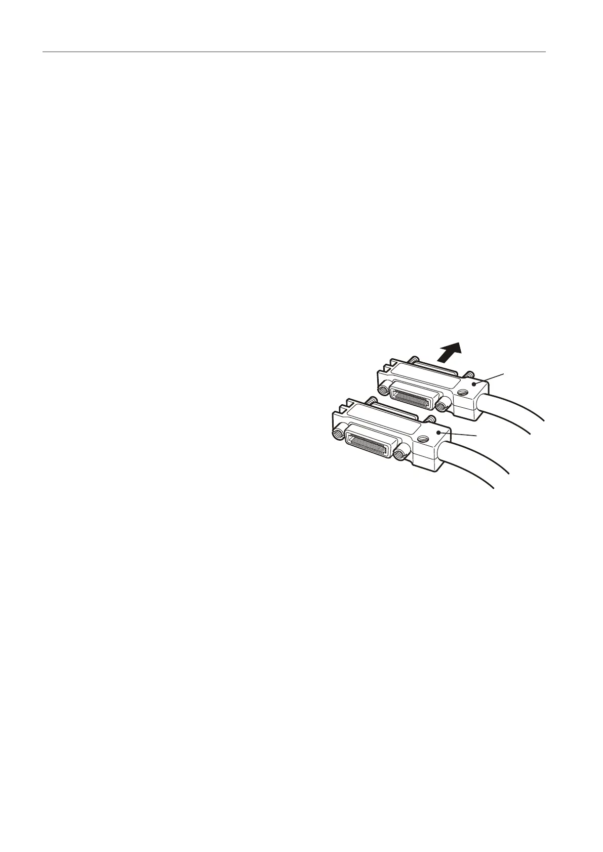
2.8.2.2 Multiple Unit Installation
To install multiple units use stacking plugs to link the
first instrument and second instrument as follows:
1. Connector to rear panel of first instrument. Refer
to illustration.
2. Connector from controller/computer. Refer to
illustration.
3. Connector to rear panel of second instrument.
Refer to illustration.
4. Connect the IEEE 488 connector on the
controller/computer and the other connector into
the next instrument.
5. Repeat this procedure for all the instruments in the system.
6. Use the Supervisor setup (communications) menu on each instrument to setup the required
communication parameters. Refer to
Section 6.6.2.2, “IEEE 488,” on page 40.
 Loading...