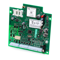
Identification of Parts
Figure 1: Parts
C ON3
LE D2
B AT +
O PE N
+
LE D1
B AT -
-
LE D4
LE D3
UA673
S E
R
IA L NU MB E R
1
44
5
3
2
8
6
9
10
11
13
12
15
14
4
tie wrap
All circuits are classified for UL installations as Power Limited/Class II Power Limited except for the battery leads which are not
power limited. Do not route any wiring over circuit boards.Maintain at least 1” (25.4mm) separation. A minimum 1/4” (6.4mm) of
separation mustbe maintained at all points between Power Limited wiring and all other non-Power Limited wiring. Route wires
as indicated above.
For ULC Commercial Fire Monitoring Installations, connections between the fire alarm control panel inputs/outputs(telephone
interface Tip/Ring or output relay contacts) and 3G4010 inputs/outputs (T1/R1, Z1-Z4, PGM1-4) shall be run in metallic conduit
within 18m(ULC) and in the same room.
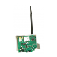
Part
1 Metal Casing
2 3G Antenna
3 Antenna Mounting Hardware
4 Anchor Screw Holes (3mm)
5 Antenna Connector
6 SIM Card Holder
7 Status LEDs (See page 9)
8 3G (HSPA) Radio Module
Part
9 PC-Link Connector
10 Tamper Switch
11 Terminal Blocks
12 Battery Leads
13 Cable Entry
14 Earth Ground Wire
15
12V/1.2Ah Battery
(not included)
This equipment 3G4010 is fixed and shall be installed by Service Persons only (Service Person is defined as a person having
the appropriate technical training and experience necessary to be aware of hazards to which that person may be exposed in
6