EasyManua.ls Logo

DSC HS2128 User Manual

DSC HS2128
261 pages
To Next Page IconTo Next Page
Page #1 background imageLoading...
Page #1 background image
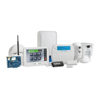
PowerSeries Neo Alarm Controller
V1.2 Reference Manual
Models:
HS2016-4/HS2016/HS2032/HS2064/HS2064 E/
HS2128/HS2128 E
WARNING: This manual contains information on limitations regarding product use and function and information on the lim-
itations as to liability of the manufacturer. The entire manual should be carefully read.

Table of Contents

Questions and Answers:

DSC HS2128 Specifications

General IconGeneral
Wi-FiNo
Number of simultaneously connected devices (max)128
Control type-
Product colorBlue
Number of door/window sensors0 pc(s)

Summary

2.0 Safety Instructions for Service Personnel

Before Installing The Equipment

Details the items to check for in the package before proceeding with the installation of the alarm equipment.

Selecting A Suitable Location For The Alarm Controller

Offers guidance on choosing an appropriate and safe location for installing the alarm controller.

SAFETY Precautions Required During Installation

Outlines critical safety measures that must be followed during the installation process.

Section 1: Introduction

1.1 About the System

Describes the PowerSeries Neo alarm panel, its features, and available models.

1.1.1 Features

Lists the capabilities of the PowerSeries Neo alarm controller, including zones, access codes, and programmable outputs.

1.1.3 Compatible Devices

Details the modules and compatible devices that can be used with the alarm controller.

Section 2: Installation

2.1 Overview of Installation Process

Outlines the sequence of steps required for a successful alarm system installation.

2.2 Alarm Controller Installation

Provides instructions for the physical mounting and installation of the alarm controller.

2.3 Wiring

Explains the wiring requirements and guidelines for connecting modules and devices.

Section 4: Configuration

4.1 Basic Configuration Steps

Lists the essential configuration tasks to perform after the initial installation.

4.3 Enrollment

Details the process of enrolling optional modules and devices into the system.

4.4 Working with Partitions

Describes how partitions divide the system into independent operational areas.

4.6 Keypad Partition Setup

Describes how to configure keypads to control individual or global partitions.

Section 5: System Operation

5.1 Arming and Disarming

Describes the various methods available for arming and disarming the system.

5.2 Partition vs. Global Keypad

Explains the difference between single partition keypads and global keypads.

5.3 Labels

Explains how to create custom labels for system identification, partitions, zones, and modules.

5.5 Keypad Function Keys

Explains how keypads have programmable function keys that can be configured for specific actions.

Section 6: Programming

6.2 Programming Methods

Outlines the different methods available for programming the alarm system.

6.3 Programming Descriptions

Provides descriptions of all alarm controller options programmable by the installer.

6.3.2 Zone Setup

Describes zone programming options, including zone types and attributes.

6.3.4 Access Codes

Details how installers program the installer, master, and maintenance codes.

Section 7: Programming Worksheets

7.1 Label Programming

Worksheets for programming system, zone, partition, and command output labels.

7.3 System Times

Covers programming various timers for the alarm system, including bell cutoff and entry/exit delays.

7.4 Access Codes

Worksheets for programming installer, master, and maintenance codes.

7.5 PGM Programming

Worksheets for programming PGM outputs, including partition assignment and timers.

Section 8: Troubleshooting

8.1 Testing

Outlines the steps for testing the alarm system's functionality.

8.2 Troubleshooting

Explains how to use the keypad to view and identify system troubles.

8.2.1 [*][2] Trouble Summary

Lists the trouble indications displayed on keypads and their detailed descriptions.

Appendix 1: Reporting Codes

Contact ID

Explains the meaning of Contact ID digits for specific signal information.

SIA Format - Level 2 (Hard Coded)

Describes the SIA communication format used by the product.

Contact ID and SIA Zone Alarm/Restore Event Codes

Defines the meaning of Contact ID and SIA zone alarm/restore event codes.

Appendix 4: Regulatory Approvals

FCC COMPLIANCE STATEMENT

Details FCC compliance requirements and potential interference issues.

UL/ULC Installations

Lists the standards the product complies with for UL/ULC installations.

UL/ULC Residential Fire and Burglary Installations:

Provides specific installation requirements for ULC residential fire and burglary systems.

UK Compliance Statement

Details UK compliance requirements and notification options.

Appendix 6: Wiring Diagrams

HS2016, HS2032, HS2064, HS2128 UL/ULC Wiring Diagram

Wiring diagram for UL/ULC installations of specified models.

Zone Wiring

Guidelines for wiring zones with SEOL or DEOL resistors.

Bell Wiring

Details the wiring for the bell output terminals, including current limitations and NFPA 72 requirements.

PGM Wiring

Provides wiring instructions for Programmable Output Modules (PGMs).

Appendix 7: Specifications

Zone Configuration

Details the supported zone types, attributes, and expansion capabilities.

Access Codes

Specifies the number of access codes and variations.

Power Supply - North America

Power supply specifications for North American models.

Battery

Details battery specifications, capacity, lifespan, and charging.

7.0.1 Locating Detectors and Escape Plan

Smoke Detectors

Offers guidance on the placement and installation of smoke detectors.

Fire Escape Planning

Provides guidance on developing and rehearsing a family escape plan.

7.0.2 Limited Warranty

7.0.3 SOFTWARE PRODUCT LICENSE

7. LIMITED WARRANTY

Related product manuals