SLICE User’s Manual July 2017
support.dtsweb.com 6 Version 1.0i
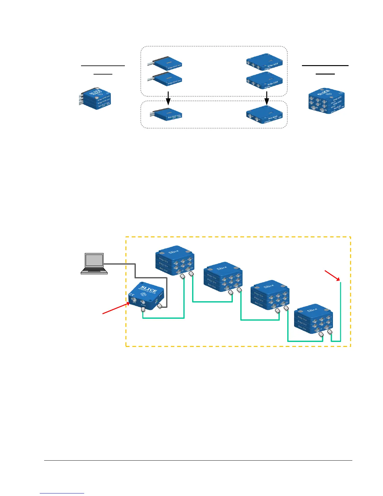
Example SLICE set-up with multiple Stacks:
• SLICE Stacks are mounted to the device under test and chained together.
• The End-of-Chain Terminal can be connected to a trigger, battery, or other
devices.
• The beginning of the chain is connected to the SLICE Interface Device, SLICE
Ethernet Interface, SLICE USB Interface or directly to the PC. PC can be
disconnected after arming for standalone operation.
• Up to 4 SLICE Stacks can be in any one chain.
• SLICE Distributor (not shown) allows for up to 4 SLICE chains for hundreds of
channel in one set-up.
SLICE
Interface
Device
PC provides
USB control
Many options:
• Battery
• Trigger input
• Monitor status
• Up to 4 Stacks
Device Under Test
Example: Crash dummy, aircraft wing, vehicle chassis,
industrial machinery, bridge structure, etc.