SLICE User’s Manual July 2017
support.dtsweb.com 7 Version 1.0i
2.3. SLICE Basic Hardware Components
Below are the basic components of a SLICE system. You will have some subset of
these depending on your application or what was ordered.
The table below provides an overview of the types of SLICE modules available. Some
modules are only available in the MICRO or NANO version.
One needed for each SLICE Stack
3 channels of piezo-resistive and voltage
sensor inputs.
3 channels of piezo-electric sensor inputs
Bridge SLICE with integrated 3-axis
accelerometer
Bridge SLICE with integrated 3-axis Angular
Rate Sensor
2-cell LiPo battery connected to bottom of
Base+ SLICE
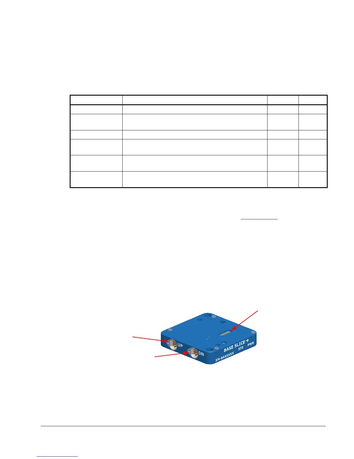
2.3.1. Base+ SLICE
See Appendix A for detailed specifications. See the DTS Support site for
information on how to update firmware.
You must have at least one Base+ SLICE for any SLICE system. The Base+
SLICE is at the bottom of the SLICE Stack and has these components:
• Microprocessor
• 16 GB flash data memory standard (15 GB available for data storage)
• USB hub
• Power conditioning
• Control signals
A Base+ SLICE MICRO is shown below.
Note: For original Base SLICE specifications, see Version 1.0g of this manual.
Connector to
Bridge SLICE or