For safe, efficient operation, the vent damper and all flue
product carrying areas of the appliance must be checked
annually byyou, with particular attention given to deterioration
from corrosion or other sources. If you see corrosion or other
deterioration,contactyour heatingcontractorfor repairs. Check
vent damper operation as follows:
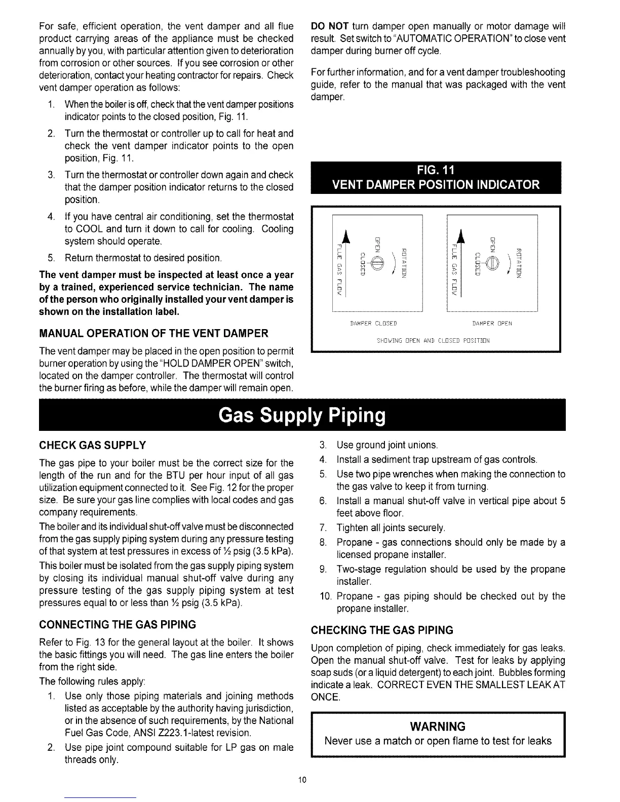
1. When the boilerisoff, checkthatthe ventdamper positions
indicator points to the closed position, Fig. 11.
2. Turn the thermostat or controller up to call for heat and
check the vent damper indicator points to the open
position, Fig. 11.
3. Turn the thermostat or controller down again and check
that the damper position indicator returns to the closed
position.
4. If you have central air conditioning, set the thermostat
to COOL and turn it down to call for cooling. Cooling
system should operate.
5. Return thermostat to desired position.
The vent damper must be inspected at least once a year
by a trained, experienced service technician. The name
ofthe person who originally installed your vent damper is
shown on the installation label.
MANUAL OPERATION OF THE VENT DAMPER
The vent damper may be placed in the open position to permit
burner operation by using the "HOLD DAMPER OPEN" switch,
located on the damper controller. The thermostat will control
the burner firing as before, while the damper will remain open.
DO NOT turn damper open manually or motor damage will
result. Set switchto "AUTOMATIC OPERATION" to close vent
damper during burner off cycle.
Forfurther information, and for a vent damper troubleshooting
guide, refer to the manual that was packaged with the vent
damper.
z
DAMPER CLOSED DAMPER DPEN
SHOWING OPEN AND CLOSED POSITION
CHECK GAS SUPPLY
The gas pipe to your boiler must be the correct size for the
length of the run and for the BTU per hour input of all gas
utilizationequipment connected to it. See Fig. 12for the proper
size. Be sure your gas line complies with local codes and gas
company requirements.
The boilerand its individualshut-off valve must bedisconnected
from the gas supply piping system during any pressure testing
of that system attest pressures inexcess of ½ psig (3.5 kPa).
This boiler must be isolated from the gas supply piping system
by closing its individual manual shut-off valve during any
pressure testing of the gas supply piping system at test
pressures equal to or tessthan ½ psig (3.5 kPa).
CONNECTING THE GAS PIPING
Refer to Fig. 13 for the general layout at the boiler. It shows
the basic fittings you will need. The gas line enters the boiler
from the right side.
The following rules apply:
1. Use only those piping materials and joining methods
listed as acceptable by the authority having jurisdiction,
or in the absence of such requirements, by the National
Fuel Gas Code, ANSI Z223.1-1atestrevision.
2. Use pipe joint compound suitable for LP gas on male
threads only.
3. Use ground joint unions.
4. Install a sediment trap upstream of gas controls.
5. Use two pipe wrenches when making the connection to
the gas valve to keep it from turning.
6. Install a manual shut-off valve in vertical pipe about 5
feet above floor.
7. Tighten all joints securely.
8. Propane - gas connections should only be made by a
licensed propane installer.
9. Two-stage regulation should be used by the propane
installer.
10. Propane - gas piping should be checked out by the
propane installer.
CHECKING THE GAS PIPING
Upon completion of piping, check immediately for gas leaks.
Open the manual shut-off valve. Test for leaks by applying
soap suds (ora liquiddetergent) to each joint. Bubblesforming
indicate a leak. CORRECT EVEN THE SMALLEST LEAKAT
ONCE.
I WARNING I
Never use a match or open flame to test for leaks
10