probe type low water cut offs, this may occur each time the
low water cut off detects a low water condition. If this is the
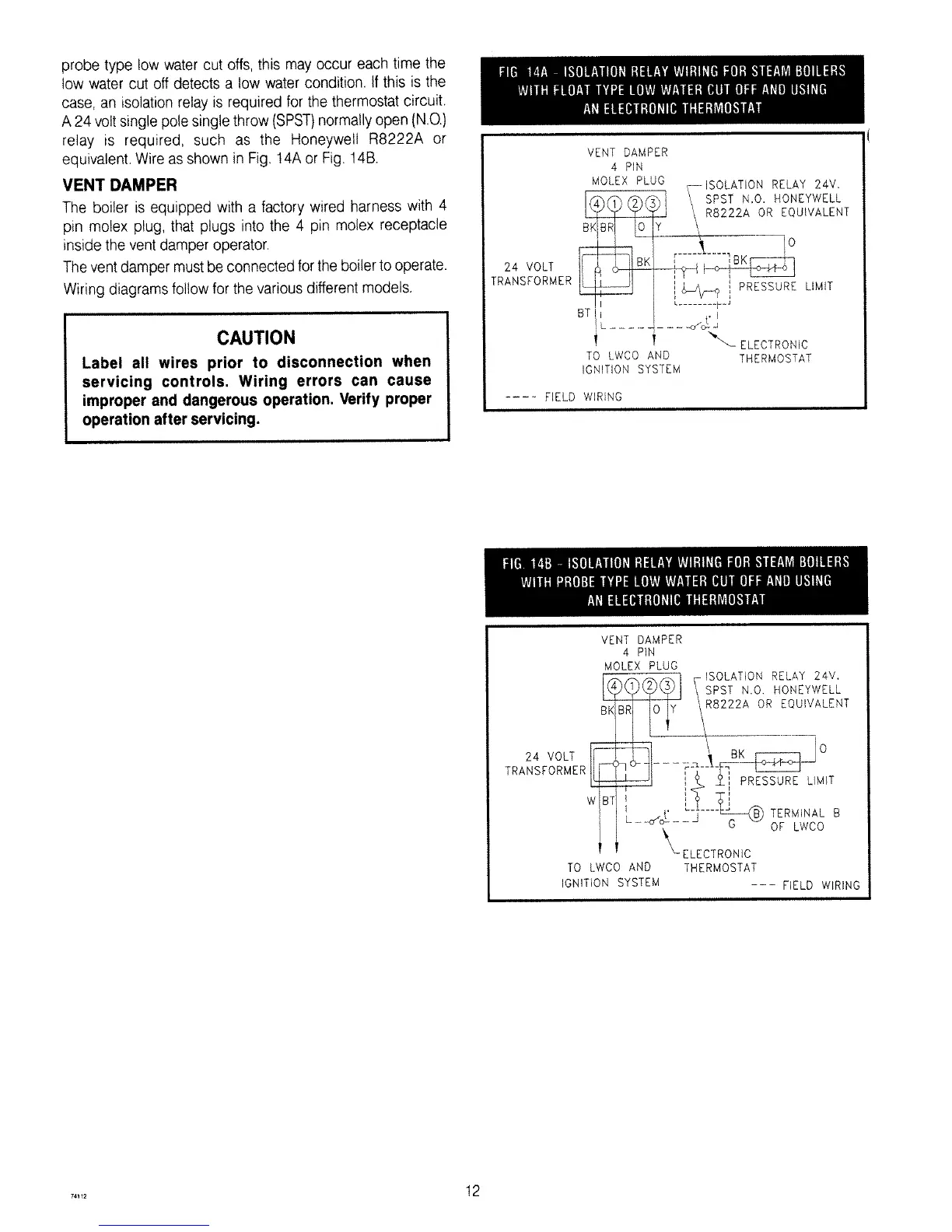
case, an isolation relay is required for the thermostat circuit.
A 24 volt single pole single throw (SPST)normally open (NO)
relay is required, such as the Honeywell R8222A or
equivalent. Wire as shown in Fig. 14A or Fig. 14B.
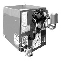
VENT DAMPER
The boiler is equipped with a factory wired harness with 4
pin molex plug, that plugs into the 4 pin molex receptacle
inside the vent damper operator.
Thevent damper must be connected for theboiler to operate.
Wiring diagrams follow for the various different models.
CAUTION
Label all wires prior to disconnection when
servicing controls. Wiring errors can cause
improper and dangerous operation. Verify proper
operation after servicing.
VENT DAMPER
4 PIN
24 VOLT
TRANSFORMER
T "_\_ ELECTRONIC
TO LWCO AND THERMOSTAT
IGNITION SYSTEM
..... FIELD WIRING
VENT DAMPER
4 PIN
MOLEX PLUG
__y _ ISOLATION RELAY 24V.
\SPST N,O, HONEYWELL
I J \R8222A OR EQUIVALENT
\
24 VOLT IIF .... _::__ -K---_ -_0
TRANSFORMER !m Z-IPRESSURELIMIT
wBT, Ti
I / _t" _"'--_ TERMINAL B
/ _- c<o--- G OF LWCO
1 _- ELECTRONIC
TO WCO AND THERMOSTAT
IGNITION SYSTEM --- FIELD WIRING
..... 12