ADJUST PILOT BURNER
Pilotflameshouldsurround3/8" to 1/2" ofthepilot sensor.Refer
to Fig.19.If flameneedsadjusting,do it asfoltows:
1.Removescrewcoveroverpilotadjustingscrew.
2.Insertsmallscrewdriverandadjustflameasneeded.Turnscrew
counterclockwiseto increaseflame, clockwiseto decrease.
3.Replacescrewcoveroverpilot adjustingscrew.
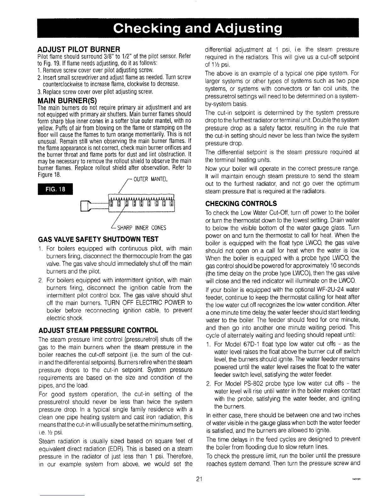
MAIN BURNER(S)
Themain burnersdo not requireprimaryair adjustmentandare
notequippedwith primaryair shutters.Mainburnerflamesshould
form sharpblueinnerconesin a softer blueoutermantel,with no
yellow.Puffsof air from blowingon the flameor stamping onthe
floor will causetheflamesto turn orangemomentarily.Thisis not
unusual.Remainstill when observingthe main burnerflames. If
theflameappearanceis notcorrect,checkmainburnerorificesand
the burnerthroat andflame portsfor dustand lint obstruction. It
maybenecessaryto removethe rollout shieldto observethemain
burnerflames.Replacerollout shield after observation.Referto
Figure18.
ARPINNERCONES
GAS VALVE SAFETY SHUTDOWN TEST
1. For boilers equipped with continuous pilot, with main
burners firing, disconnect the thermocouple from the gas
valve.The gas valve should immediately shut off the main
burners and the pilot.
2. For boilers equipped with intermittent ignition, with main
burners firing, disconnect the ignition cable from the
intermittent pilot control box. The gas valve should shut
off the main burners. TURN OFF ELECTRICPOWERto
boiler before reconnecting ignition cable, to prevent
electric shock.
ADJUST STEAM PRESSURE CONTROL
The steam pressure limit control (pressuretro!) shuts off the
gas to the main burners when the steam pressure in the
boiler reaches the cut-off setpoint (i.e. the sum of the cut-
inand thedifferential setpoints).Burners retirewhen the steam
pressure drops to the cut-in setpoint. System pressure
requirements are based on the size and condition of the
pipes, and the load.
For good system operation, the cut-in setting of the
pressuretrol should never be less than twice the system
pressure drop. In a typical single family residence with a
clean one pipe heating system and cast iron radiation, this
meansthatthe cut-in will usuallybe setat the minimum setting,
i.e. '/2psi.
Steam radiation is usually sized based on square feet of
equivalent direct radiation (EDR). This is based on a steam
pressure in the radiator of just tess than 1 psi. Therefore,
in our example system from above, we would set the
differential adjustment at 1 psi, i.e. the steam pressure
required in the radiators. This will give us a cut-off setpoint
of 11/2psi.
The above is an example of a typical one pipe system. For
larger systems or other types of systems such as two pipe
systems, or systems with convectors or fan coil units, the
pressuretrol settings will need to be determined on a system-
by-system basis.
The cut-in setpoint is determined by the system pressure
drop tothe furthest radiator orterminal unit.Double the system
pressure drop as a safety factor, resulting in the rule that
the cut-in setting should never be less than twice the system
pressure drop.
The differential setpoint is the steam pressure required at
the terminal heating units.
Now your boiler wil! operate in the correct pressure range.
It will maintain enough steam pressure to send the steam
out to the furthest radiator, and not go over the optimum
steam pressure that is required at the radiators.
CHECKING CONTROLS
Tocheck the Low Water Cut-Off, turn off power to the boiler
or turn the thermostat down to the lowest setting. Drain water
to below the visible bottom of the water gauge glass. Turn
power on and turn the thermostat to call for heat. When the
boiler is equipped with the float type LWCO,the gas valve
should not open on a cal! for heat when the water is low.
When the boiler is equipped with a probe type LWCO,the
gas control should be powered for approximately 10seconds
(thetime delay on the probe type LWCO),then the gas valve
wil! close and the red indicator will illuminate on the LWCQ
If your boiler is equipped with the optional WF-2U-24 water
feeder, continue to keep the thermostat calling for heat after
the lowwater cut off recognizes the low watercondition. After
a one minute time delay,thewater feeder should startfeeding
water to the boiler. The feeder should feed for one minute,
and then go into another one minute waiting period. This
cycle ofalternately waiting and feeding should repeat until:
1. For Model 67D-1 float type low water cut offs - as the
water level raises the float above the burner cut off switch
level, the burners should ignite. The water feeder remains
powered until the water level raises the float to the water
feeder switch level,satisfying the water feeder.
2. For Model PS-802 probe type low water cut offs - the
water levelwill rise until water in the boiler makes contact
with the probe, satisfying the water feeder, and igniting
the burners.
Ineither case, there should be between one and two inches
ofwatervisible in the gauge glass when both the waterfeeder
issatisfied, and the burners are allowed to ignite.
The time delays in the feed cycles are designed to prevent
the boiler from flooding due to slow return lines.
To check the pressure limit, run the boiler untilthe pressure
reaches system demand. Then turn the pressure screw and
1 z4o_eH