Length of
Pipe - Ft.
2O
4O
60
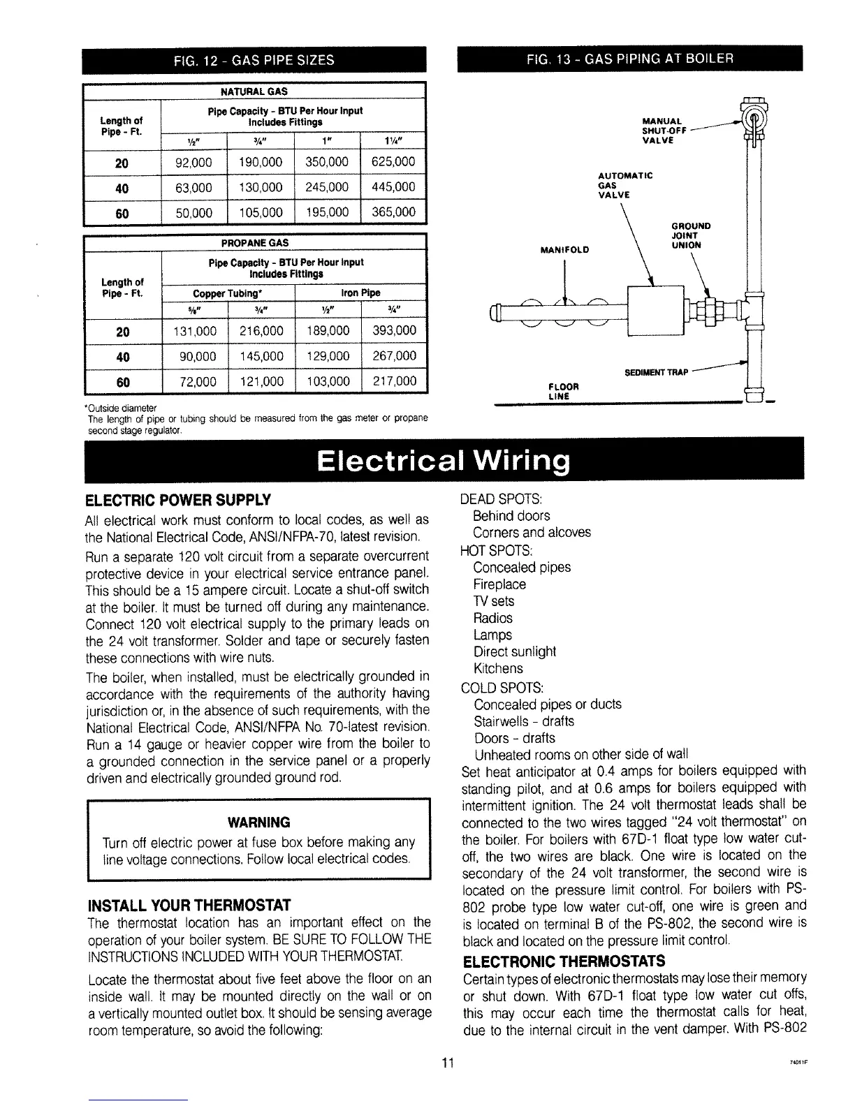
NATURAL GAS
Pipe Capacity - BTU Per Hour Input
includes Fittings
Y2" 314" 1"
92,000 190,000 350,000
63,000 130,000 245,000
50,000 105,000 195,000
1¼"
625,000
445,000
365,000
Length of
Pipe- Ft.
20
40
60
PROPANE GAS
Pipe Capacity - BTU Per Hour input
includes Fittings
CopperTubing*
%- ¾-
131,000 2!6,000
90,000 145,000
72,000 121,000
Iron Pipe
½- ¾-
189,000 393,000
129,000 267,000
103,000 217,000
*Outside diameter
The length of pipe or tubing should be measured from the gas meter or propane
second stage regulator.
VALVE
iZT'" tl
\ o=oLL
F LOOR SEDIMENT TRAP
LINE ........."___
ELECTRIC POWER SUPPLY
All electrical work must conform to local codes, as wel! as
the National Electrical Code, ANSt/NFPA-70, latest revision.
Run a separate 120 volt circuit from a separate overcurrent
protective device in your electrical service entrance panel.
This should be a 15 ampere circuit. Locate a shut-off switch
at the boiler. It must be turned off during any maintenance.
Connect 120 volt electrical supply to the primary leads on
the 24 volt transformer. Solder and tape or securely fasten
these connections with wire nuts.
The boiler, when installed, must be electrically grounded in
accordance with the requirements of the authority having
jurisdiction or, in the absence of such requirements, with the
National Electrical Code, ANSI/NFPA No. 70-latest revision.
Run a 14 gauge or heavier copper wire from the boiler to
a grounded connection in the service panel or a properly
driven and electrically grounded ground rod.
WARNING
Turn off electric power at fuse box before making any
line voltage connections. Follow local electrical codes.
INSTALL YOUR THERMOSTAT
The thermostat location has an important effect on the
operation of your boiler system. BE SURETO FOLLOW THE
INSTRUCTIONSINCLUDEDWITH YOURTHERMOSTAT,
Locate the thermostat about five feet above the floor on an
inside wall. It may be mounted directly on the wall or on
a vertically mounted outlet box. It should be sensing average
room temperature, so avoidthe following:
DEAD SPOTS:
Behind doors
Corners and alcoves
HOTSPOTS:
Concealed pipes
Fireplace
TVsets
Radios
Lamps
Direct sunlight
Kitchens
COLD SPOTS:
Concealed pipes or ducts
Stairwells - drafts
Doors - drafts
Unheated rooms on other side of wall
Set heat anticipator at 0.4 amps for boilers equipped with
standing pilot, and at 0.6 amps for boilers equipped with
intermittent ignition. The 24 volt thermostat leads shall be
connected to the two wires tagged "24 volt thermostat" on
the boiler. For boilers with 67D-1 float type tow water cut-
off, the two wires are black. One wire is located on the
secondary of the 24 volt transformer, the second wire is
located on the pressure limit control. For boilers with PS-
802 probe type low water cut-off, one wire is green and
is located on terminal B of the PS-802, the second wire is
black and located on the pressure limit control.
ELECTRONIC THERMOSTATS
Certaintypes of electronic thermostats may lose theirmemory
or shut down. With 67D-1 float type low water cut offs,
this may occur each time the thermostat calls for heat,
due to the internal circuit in the vent damper. With PS-802
t 74o11F