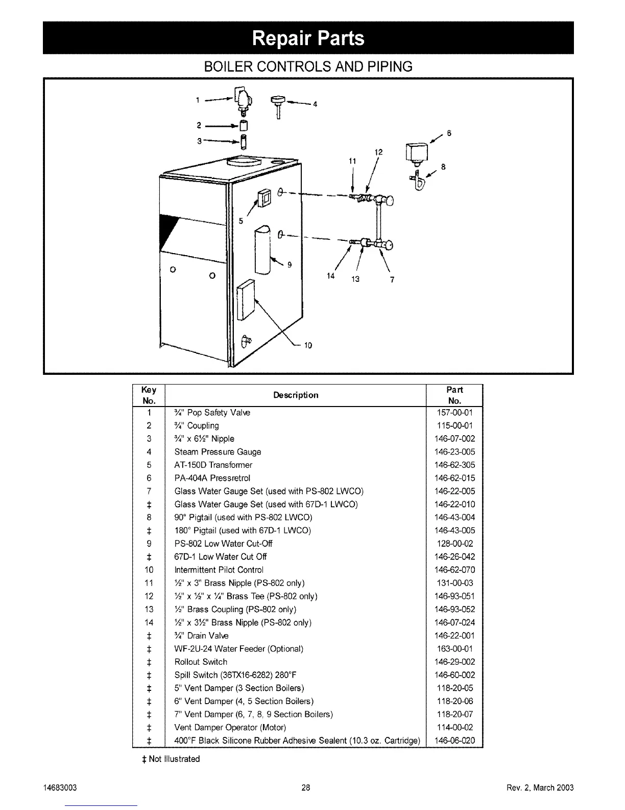
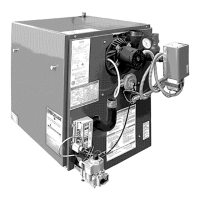
BOILER CONTROLS AND PIPING
5
6::
14 13 7
10
f
Description
Key
No.
1 ¾" Pop Safety Valve
2 ¾" Coupling
3 ¾" x 6%" Nipple
4 Steam Pressure Gauge
5 AT-150D Transformer
6 PA-404A Pressretrol
7 Glass Water Gauge Set (used with PS-802 LWCO)
:[: Glass Water Gauge Set (used with 67D-1 LWCO)
8 90° Pigtail (used with PS-802 LWCO)
180 ° Pigtail (used with 67D-1 LWCO)
9 PS-802 Low Water Cut-Off
67D-1 Low Water Cut Off
10 Intermittent Pilot Control
11 %" x 3" Brass Nipple (PS-802 only)
12 %" x %" x ¼" Brass Tee (PS-802 only)
13 %" Brass Coupling (PS-802 only)
14 %" x 3%" Brass Nipple (PS-802 only)
:[: ¾" Drain Valve
_: WF-2U-24 Water Feeder (Optional)
:I: Rollout Switch
$ Spill Switch (36TX16-6282) 280°F
$ 5" Vent Damper (3 Section Boilers)
:1: 6" Vent Damper (4, 5 Section Boilers)
7" Vent Damper (6, 7, 8, 9 Section Boilers)
:1: Vent Damper Operator (Motor)
:1: 400°F Black Silicone Rubber Adhesive Sealent (10.3 oz. Cartridge)
Part
No.
157-00-01
115-00-01
146-07-002
146-23-005
146-62-305
146-62-015
146-22-005
146-22-010
14643-004
146-43-005
128-00-02
146-26-042
146-62-070
131-00-03
146-93-051
146-93-052
146-07-024
146-22-001
163-00-01
146-29-002
146-60-002
118-20-05
118-20-06
118-20-07
114-00-02
146-06-020
:1:Not Illustrated
14683003 28 Rev. 2, March 2003