25
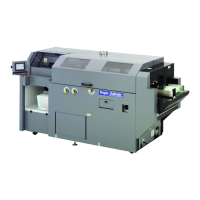
2. Outline of each block
1. Switching Power
Converts AC110V / 220V into DC 5V and DC 12 V.
2. Control Panel ( TG200B1 )
Displays the current status of the machine.
3. Clamp Station Right Sensor ( LS1 )
Detects and locates the clamp station at its home position.
4. Clamp Station Left Sensor ( LS2 )
Detects and stops the clamp station to the left of the machine.
5. Nipping Station Sensor ( LS3 / LS4 )
LS3: detects the lowest point of the nipping station surface.
LS4: detects the highest point of the nipping station surface.
6. Clamp Inner Page Sensor ( SN1 )
Detects when pages are placed in the clamp station.
7. Nipping Cover Sensor ( SN2 )
Detects when cover page is placed on the nipping station.
8. Half Temperature Sensor ( TEMP2 )
Sets the lowest temperature of the glue tank when the machine has been switched to
“STANDBY” mode.
9. CPU ( TG200A1 )
Controls the operating procedures, the input/output and the error message handling
of the machine.
10. SSR ( TG200C2 )
Controls the driving components for the motors and thermostat.
11. Emergency Switch
Used for stopping the machine when machine has encountered a malfunction or
abnormal operation.