1-34
12H-M12M0-0309-0
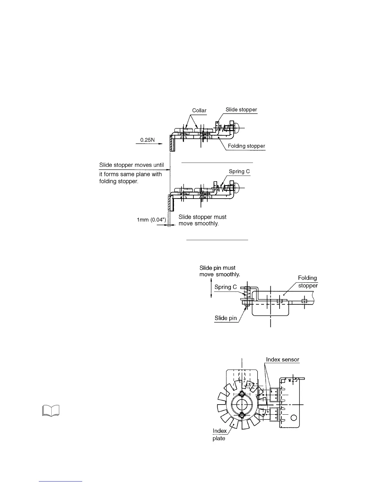
2-6-5. Adjusting the position of the folding stopper and slide stopper
q Tighten the M3 screw with a torque of 0.64 Nm (6.5 kgf • cm) and secure the collar.
w Check that when a pressure of 0.25 N (25 gf) is applied to the slide stopper using a tension gauge of 1 N (102 gf),
the slide stopper moves smoothly to the bottom regulated position, and when the tension gauge is removed, it
returns promptly to the top regulated position.
The distance moved by the slide stopper is 1 mm (0.04").
e Apply a very small amount of thread locking to the collar fixing screw from the back of the folding stopper.
(Three Bond 1401B: For preventing loosening)
Top regulated position
2-6-6. Folding stopper slide pin
A slide pin is provided at both ends of the folding stopper
so that the folding stopper moves horizontally, thus
preventing abnormal low speed movements due to load
changes and abnormal noise.
q Check that the two photointerrupters are attached
parallel to each other.
w When the screw shaft is rotated by hand, check that
the two sensors turn ON and OFF properly in the
maintenance mode.
“3. MAINTENANCE MODE” in CHAPTER 2
ELECTRICAL COMPONENTS
e Check that the folding stopper moves away from the
home position when the “+” key of the folding stopper
adjusting key on the control panel is pressed, and
towards the home position when the “–” key is
pressed.
SeeSee
2-6-7. Checking the operations of the index sensor
Bottom regulated position
 Loading...