3
2. Installation and Adjustment
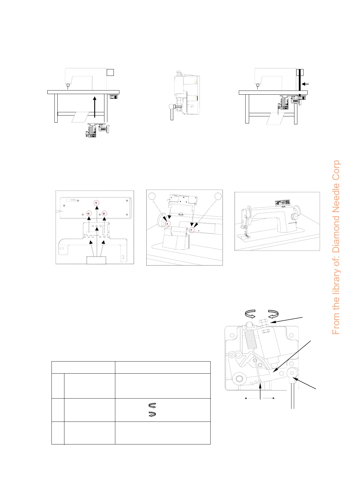
(1).Control box installation :
(2).Operation box installation :
(3). Speed control unit adjustment :
B
a). Install the motor and control box under the table b). Install the pedal with speed control unit c).Finished diagram
V-belt
Control box
and motor
Speed control
unit
Pitman rod
Components of speed control unit : see figure
A: Spring for toeing forward force adjustment
B: Bolt for heeling backward force adjustment
C: Treadle / Pedal arm
D: Pitman rod
Term of adjustment
Toeing forward
force adjustment
Heeling backward
force adjustment
Treadle stroke
adjustment
Adjustment result
Spring A moved to right = force increased
Spring A moved to left = force decreased
Bolt B turned = force decreased
Bolt B turned = force increased
Rod D secured at right = stroke is longer
Rod D secured at left = stroke is shorter
1
2
3
B
A
C
D
increase decrease
decrease
increase
Operation box
Bracket
Screw
E
F
S
P
G
H
D
B
A
C
a). Assembling the operation box on
the bracket and secure screws.
b). Unscrew screw A, B and mounting the
bracket on the machine head.
c). Remember to secure the screw A, B
and plug the operation box connector
to control box.
From the library of: Diamond Needle Corp
 Loading...