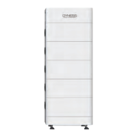
Powerbox Pro series User Manual
9
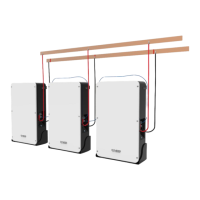
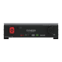
When the system is used in parallel:
This CAN/RS485 communication socket is connected to the COM
IN interface of the next Powerbox Pro through communication
cable.
(Factory default CAN communication mode)
Module 1 status indicator light
Module 2 status indicator light
Press the switch and the battery system turn on.
When the battery is in the non-use state such as storage,
transportation etc., it needs to be turn off by pressing the Reset
switch button, and the battery system will automatically sleep
after the device without external load and power for 72 hours.
Or if you need to shut down the system,firstly swich off the DC
breaker between the battery with the inverter, then press the
switch for 3s
Communication cascade port, support RS232
Table 2-4 LED status indicators
Stand-by/Char
ging/Dischargi
ng
Always on, Corresponding module
alarm or 0%<SOC≤10%
Flashing, (Corresponding module
protection be activated /
Over-discharge protection
/Over-current protection /
Temperature abnormality, etc.)
Yellow, green and red flash
alternately
All module address assignments in the
system are incomplete