Powerbox Pro series User Manual
8
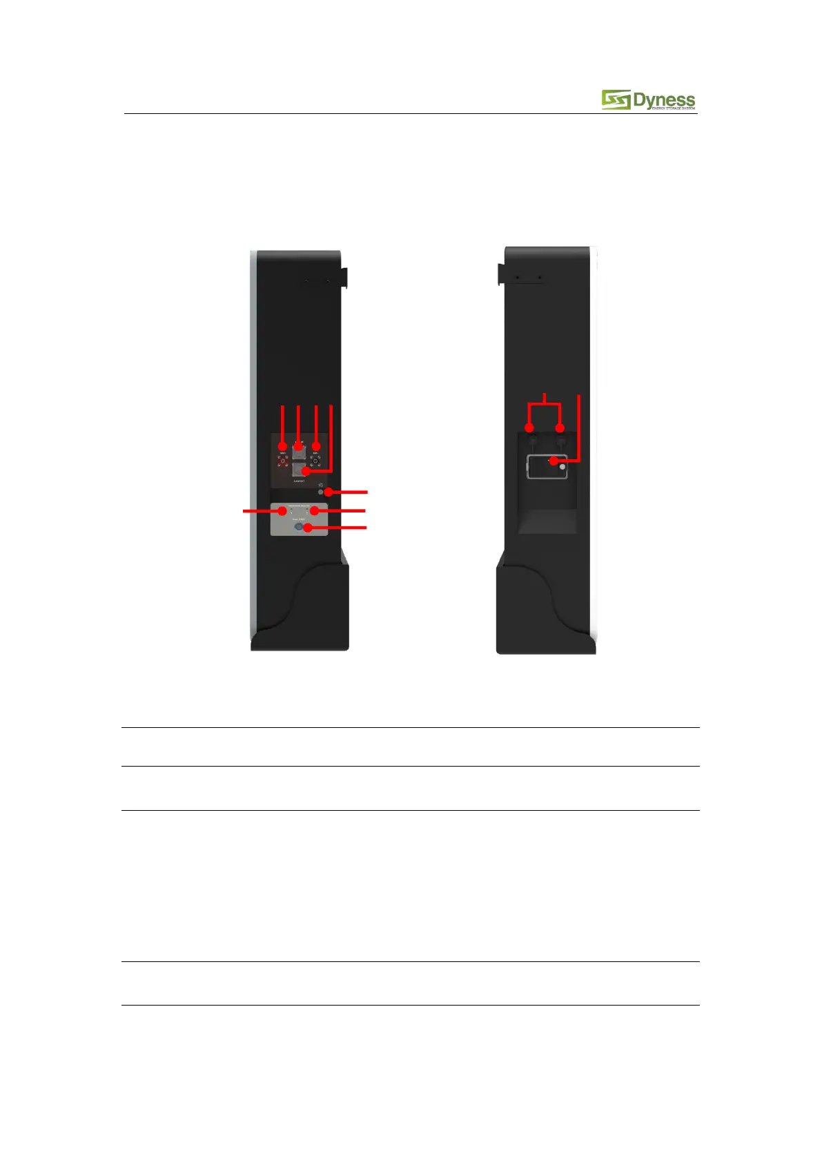
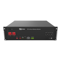
2.3 Interface Definition
This section elaborates on interface functions of the front panel of the device.
Figure2-1 Powerbox Pro the sketch of front interface.
Table 2-3 Interface Definition
The battery DC output positive pole, which is connected to the
positive pole of the inverter through the cable
When the system is used independently:
The CAN/RS485 socket is connected to the inverter CAN/RS485
interface through the communication cable.
When the system is used in parallel:
This CAN/RS485 communication socket is connected to the COM
OUT interface of the previous Powerbox Pro through
communication cable.
The battery DC output negative pole, which is connected to the
negative pole of the inverter through the cable
When the system is used independently:
This CAN/RS485 socket is a reservation interface