EasyManua.ls Logo

E.T. Systems UMPETHA - Page 7

E.T. Systems UMPETHA
30 pages
Print Icon
To Next Page IconTo Next Page
To Previous Page IconTo Previous Page
Loading...
UMPETHA 082009/072010.014
7
CABLING REQUIREMENTS
Before mounting the operator ensure your cabling and conduiting are in place to prevent any inconvenience at a later stage. Allow for
spare cabling in case of faulty cable & breakages (especially important when using low specification cable). If installing an intercom,
remember to allow for sufficient cable cores for all the uses on the system as per manufacturers cabling requirements.
1
7
8
4
1
2
4
5
3
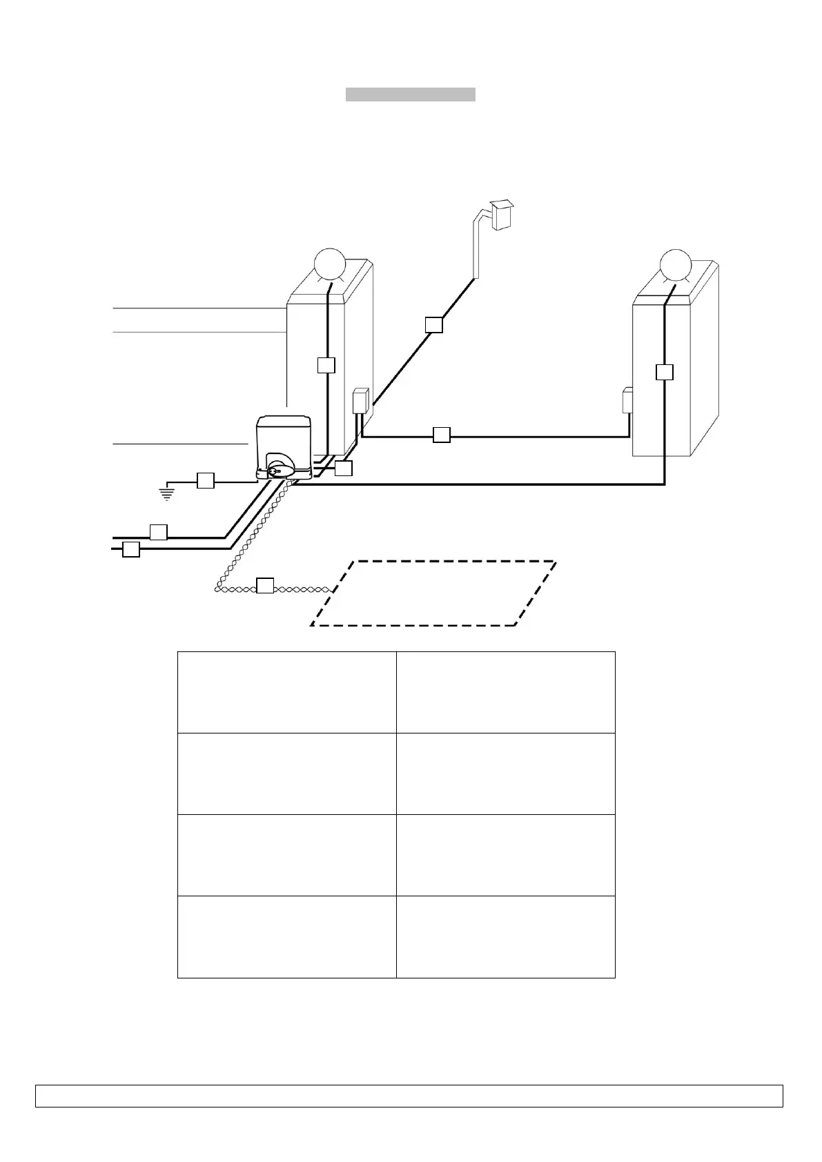
2. Safety infra-red beam power (2-core)
3. Safety infra-red beam power & switch (4-core)
4. Courtesy lights (twin + earth 1.0mm)
1. Intercom gate station (check with intercom
supplier specifications)
5. Free exit loop (1.5mm silicone insulated single
core flexible stranded)
6. Primary power: Plug in transformer model - twin:
min 0,5mm Internal in-line transformer model
(220Vac) - twin + earth: 1,0mm
7. From intercom internal equipment (check with
intercom supplier specifications)
8. Optional earth-rod for high lightning strike areas
(preferably use household earth leakage)

Related product manuals