ELECTRONIC SPEED CONTROL (36V)
Page F-3
Repair and Service Manual
Read all of Section B and this section before attempting any procedure. Pay particular attention to all Notes, Cautions and Warnings
Continuity Check
To prevent possible inju-
ry or death resulting
from a battery explo-
sion, use an insulated wrench and remove the BL-
wire from the battery to disconnect electrical power to
vehicle.
Before attempting to perform a continuity check, turn
the key switch to ‘OFF’ and place the direction selec-
tor in neutral.
If the solenoid does not function, the pedal micro switch,
neutral micro switch (direction selector switch), solenoid,
key switch and four pin connector should be checked for
continuity.
Turn the key switch to ‘OFF’ and place the direction
selector in neutral before disconnecting power by remov-
ing the B+ connection to the battery. Always use insu-
lated wrenches when working on batteries. To check
for continuity, set the DVOM to the KΩ setting and select
‘Continuity’. The meter will give an audible signal when it
detects continuity. If the meter does not have a continuity
setting, set it to KΩ, the meter will indicate “0” when it
detects continuity.
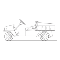
Testing a Switch for Continuity
Place one probe on one contact of the switch, place the
second probe on the second terminal of the switch (Ref
Fig. 4 on page F-3).
Actuating a normally open (NO) switch will cause the
DVOM to show “0” or give an audible indication when the
switch is operated. A normally closed (NC) switch will
cause the meter to show “0” or give an audible indication
when the probes are attached without activating switch.
The audible indicator will stop and the meter display will
indicate a value greater than “0” when the switch is acti-
vated.
The change in display or audible indicator demonstrates
that the switch is functioning.
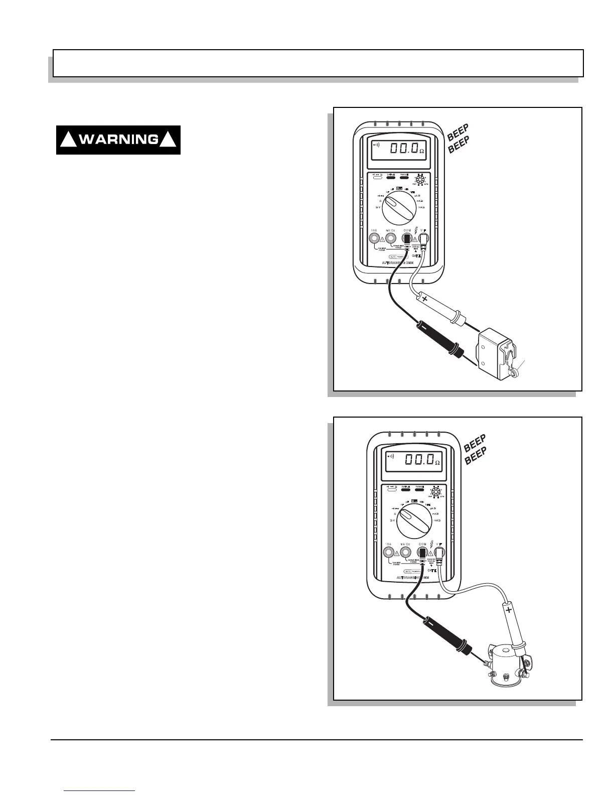
Testing a Solenoid for Continuity
Place one probe on one of the large terminals and the
other probe on the second large terminal (Ref Fig. 5 on
page F-3). If the meter shows “0” or gives an audible indi-
cation, the solenoid terminals are “welded” closed and
the solenoid must be replaced.
If the continuity test indicates that contacts are not
“welded” and the wiring to the solenoid coil is good, the
coil has failed and the solenoid must be replaced.
! !
Fig. 4 Continuity Check of Switch
Fig. 5 Continuity Check of Solenoid
Press to
activate
switch
 Loading...


