ELECTRONIC SPEED CONTROL (36V)
Page F-4
Repair and Service Manual
Read all of Section B and this section before attempting any procedure. Pay particular attention to all Notes, Cautions and Warnings
TROUBLESHOOTING DIAGRAMS
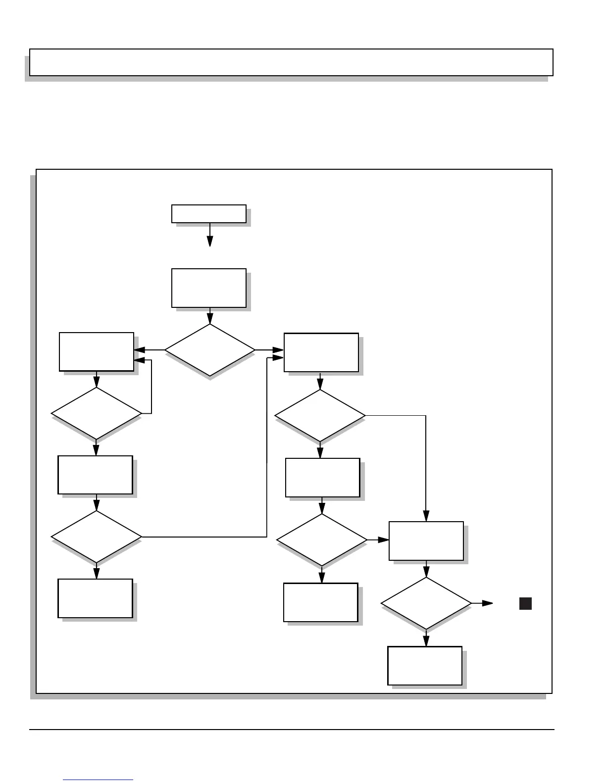
The simplified troubleshooting diagram is a quick ESC
diagnosis (Ref Fig. 6 on page F-4). Use this diagram to
perform initial troubleshooting. Follow the indicated step
numbers to the information in the detailed troubleshoot-
ing diagram.
It is vital to the safety of the technician and assistants
that all warnings and safety procedures in this section be
followed.
Fig. 6 Simplified Troubleshooting Diagram
Solenoid Click?
Solenoid Click?
Yes
Yes
Yes
Key ON
Direction Selector in F
Pedal Down
Does Not Run
Check
Vehicle
Operation
Go to Step 16
ITS
(Steps 23 - 35)
Go to Step 37
Power Circuit
(Steps 37 - 46)
Go to Step 1
Control Circuit
(Steps 1 - 22)
Vehicle Operates?
No
No
No
No
No
No
Vehicle Operates?
Stop
Yes
Stop
Vehicle Operates?
Yes
Stop
Raise rear of vehicle
Verify wheels turn freely
Key ON
Direction Selector in F
Pedal fully depressed
Reference
Voltage?
Yes
Voltage Between
Controller B+ &
Controller M-
Electronic Speed Control
Simplified Troubleshooting
1206 Controller
Go to
1

 Loading...


